 Pronto Energy
- Products Our Products
Low-voltage protection for distribution boards and photovoltaic systems, plus related accessories.
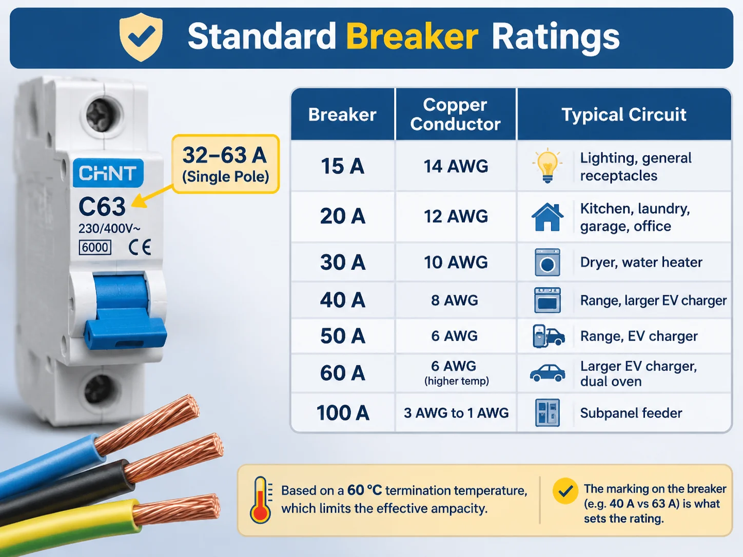
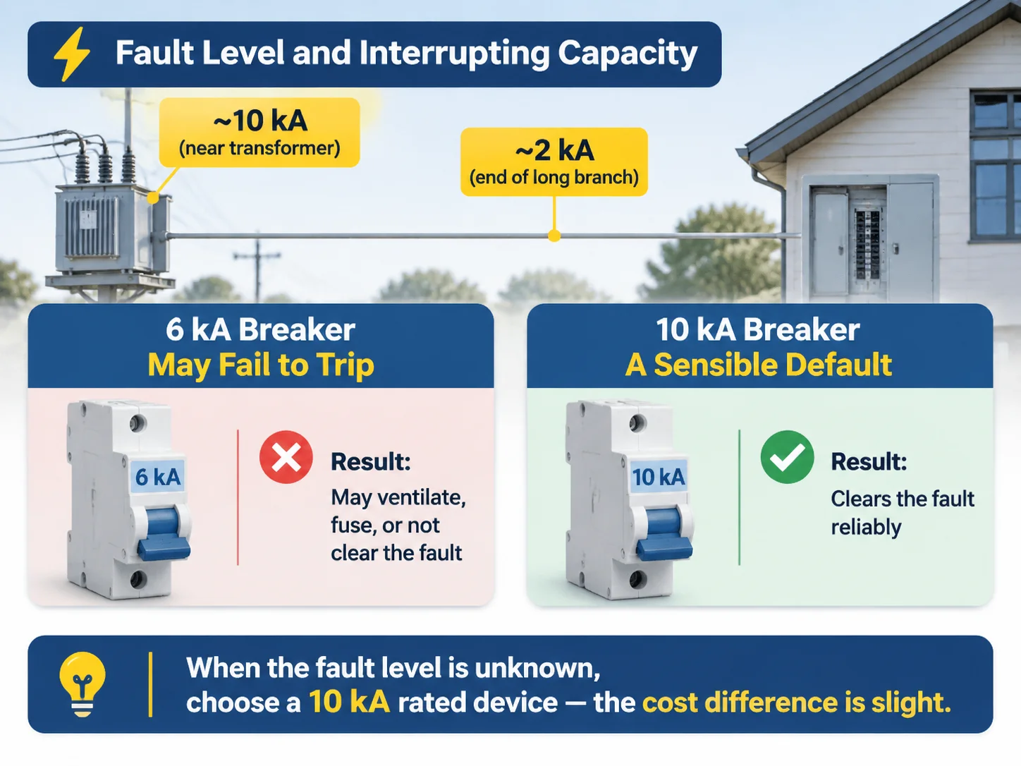
Sourcing & SupportMiniature Circuit BreakersAC and DC miniature circuit breakers from 6A to 125A, 1P to 4P, 3–15kA, Type B/C/D, for distribution boards and solar PV strings.All Products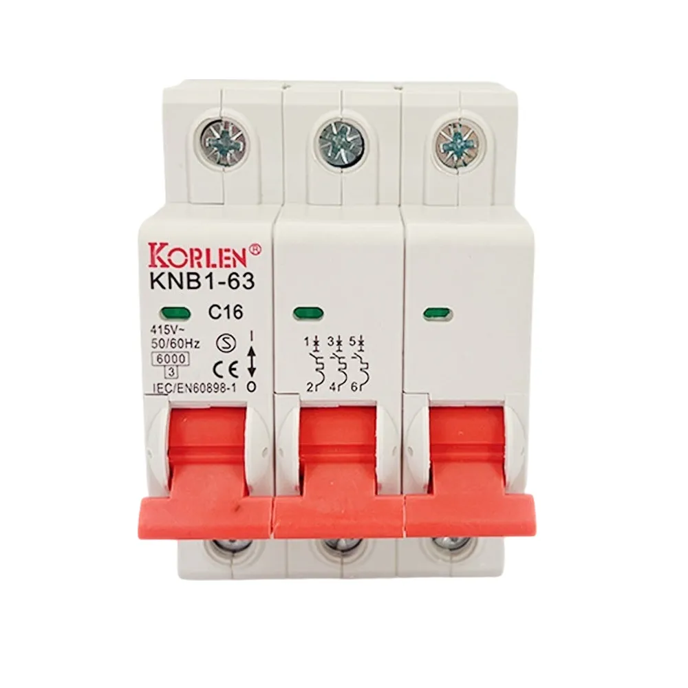 32–63A MCB 3P 3kA Type B/C/D KNB1-63 Korlen
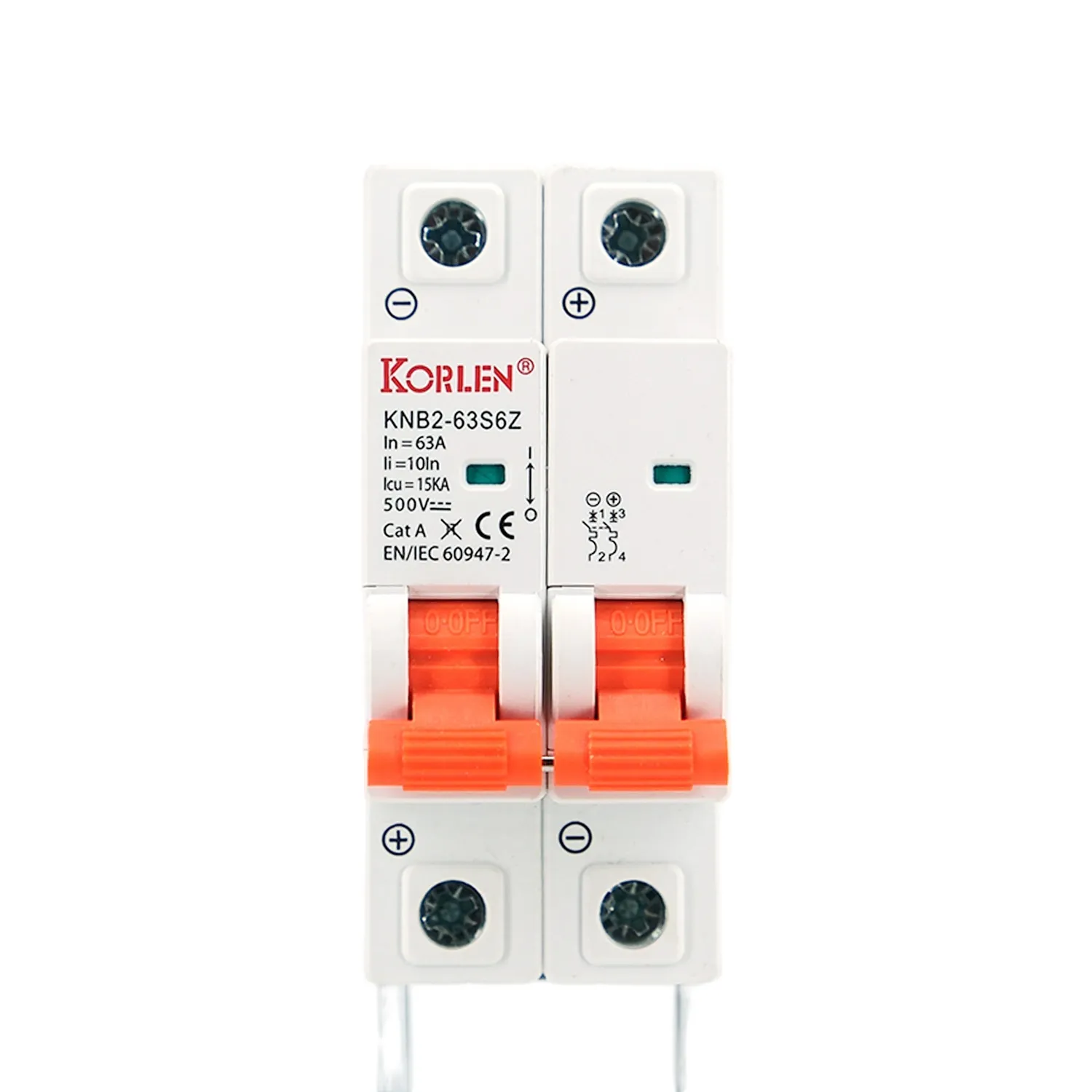 32–63A PV DC MCB 2P 15kA KNB2-63S6Z Korlen
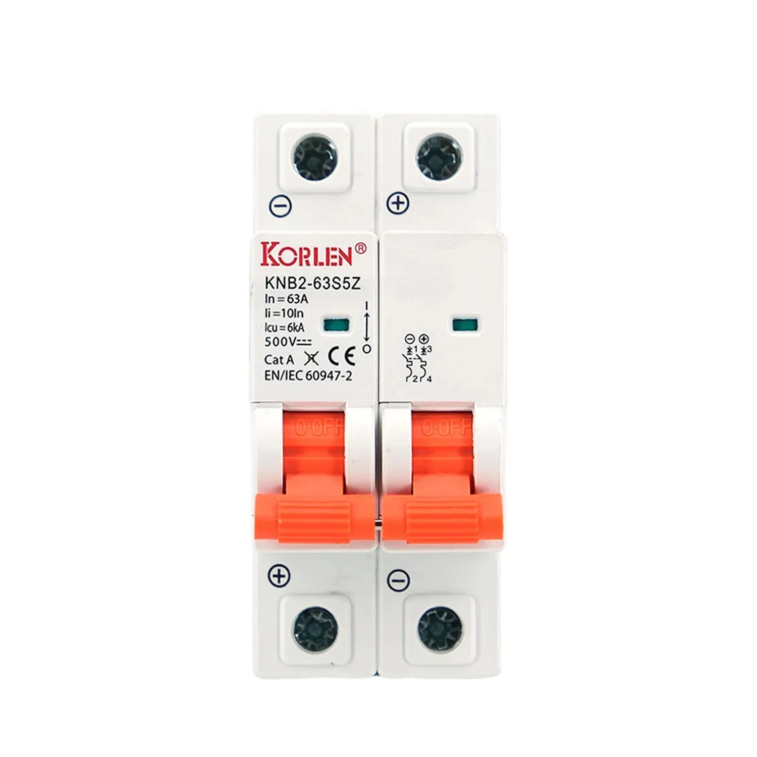 6–25A DC Miniature Circuit Breaker 2P 6kA KNB2-63S5Z Korlen
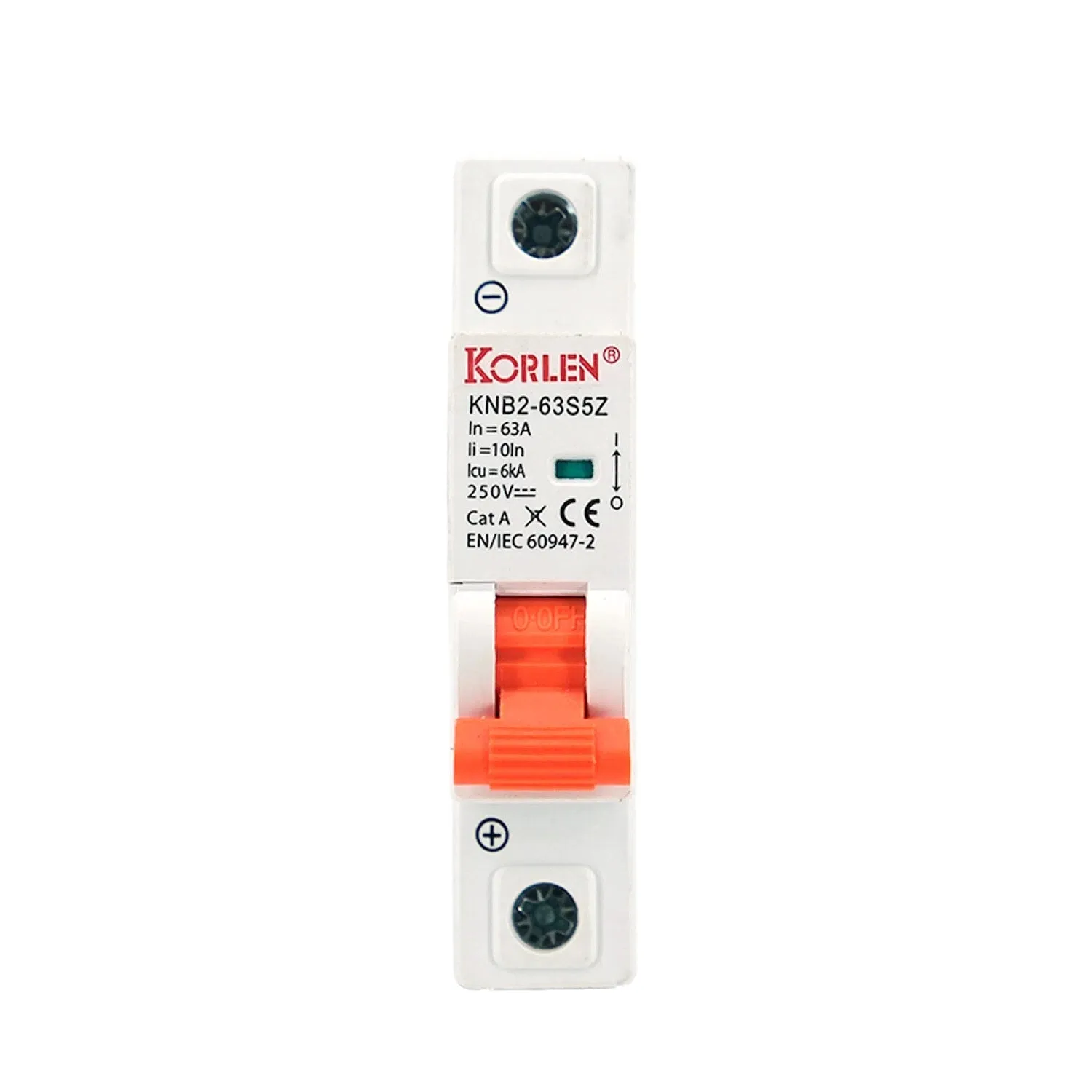 DC Miniature Circuit Breaker 1P 6–25A 6kA KNB2-63S5Z Korlen
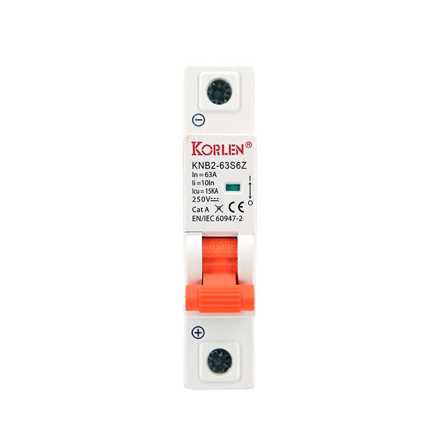 DC Miniature Circuit Breaker 1P 6–25A DC Rated KNB2-63S6Z Korlen
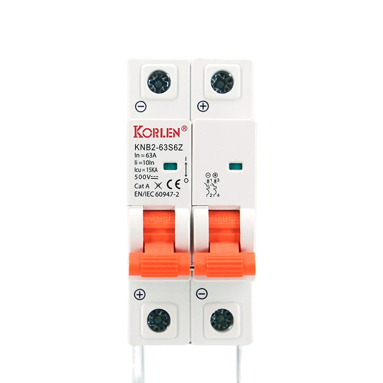 DC Miniature Circuit Breaker 2P 6–25A for Solar PV Strings KNB2-63S6Z Korlen
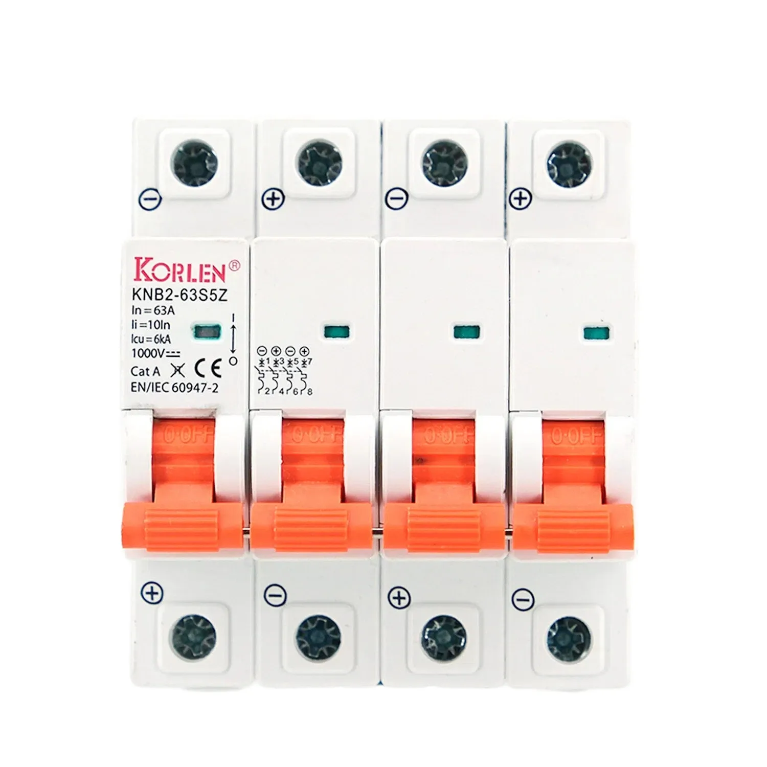 DC Miniature Circuit Breaker 4P 6–25A 6kA for Battery and PV Circuits KNB2-63S5Z Korlen
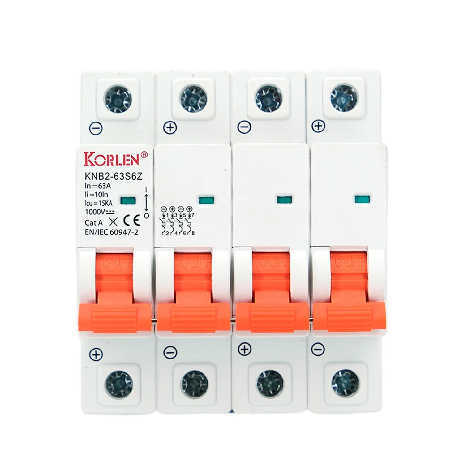 DC Miniature Circuit Breaker Four Pole 6–25A 15kA KNB2-63S6Z Korlen
Molded Case Circuit BreakersAC and DC moulded case breakers from 16A to 2000A, 2P to 4P, up to 690V AC and 1500V DC, for main and sub-main distribution.All Products
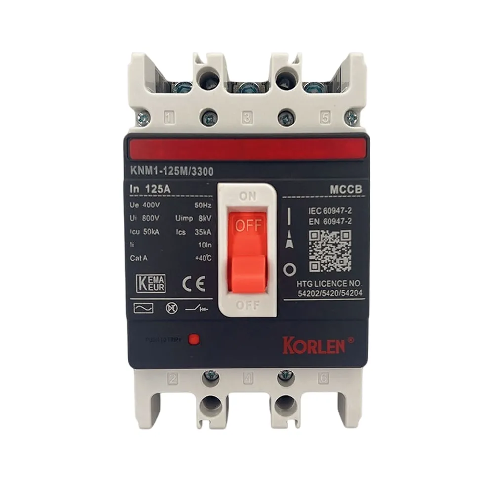 1000–1600A 3P MCCB 690 V AC KNM1 Korlen
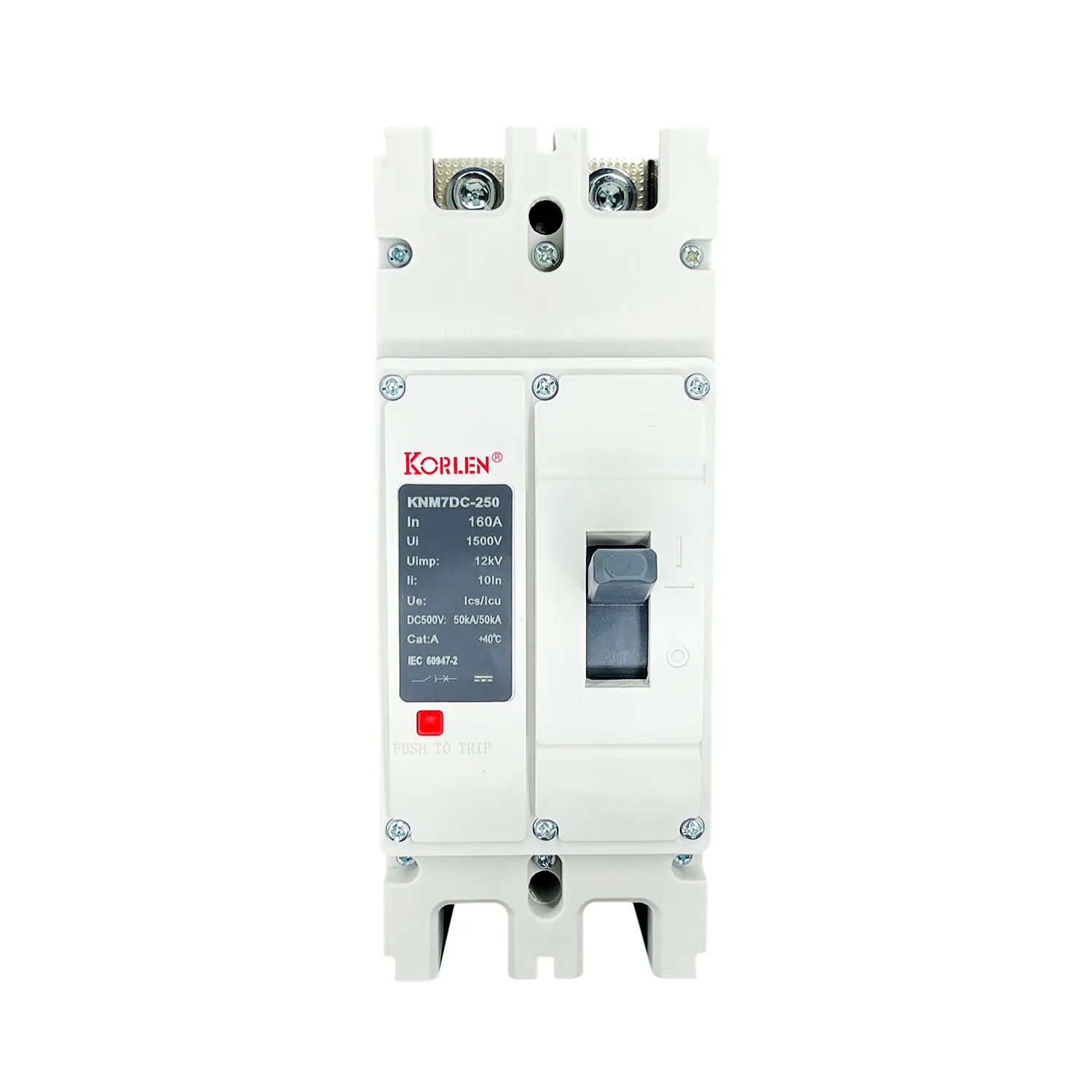 250–400A DC MCCB 2P / 3P 500 V DC KNM7DC Korlen
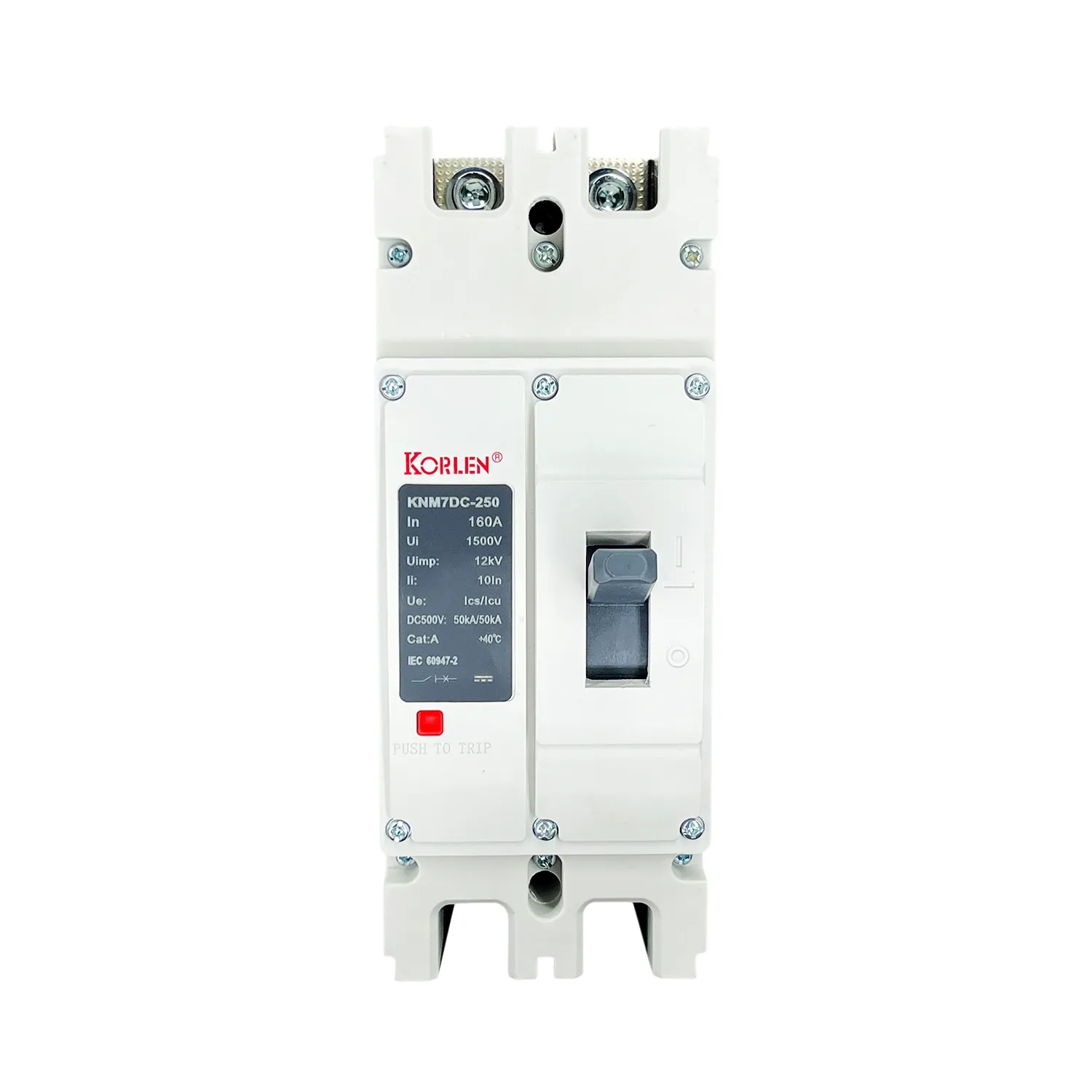 630–800A DC Moulded Case Breaker 2P / 3P 1000 V DC KNM7DC Korlen
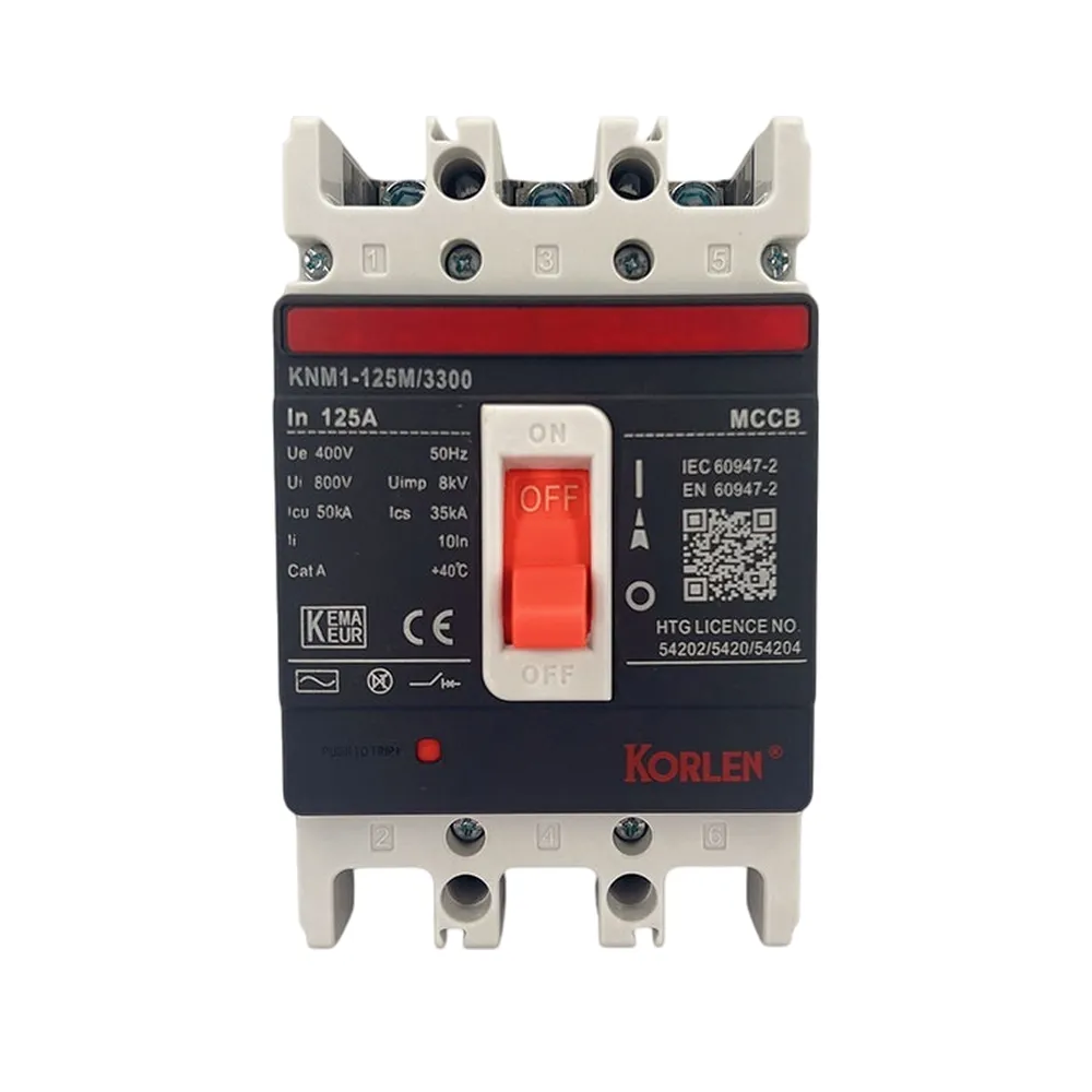 Compact Circuit Breaker 3P 2000A 690 V AC DIN Rail or Panel Mount KNM1 Korlen
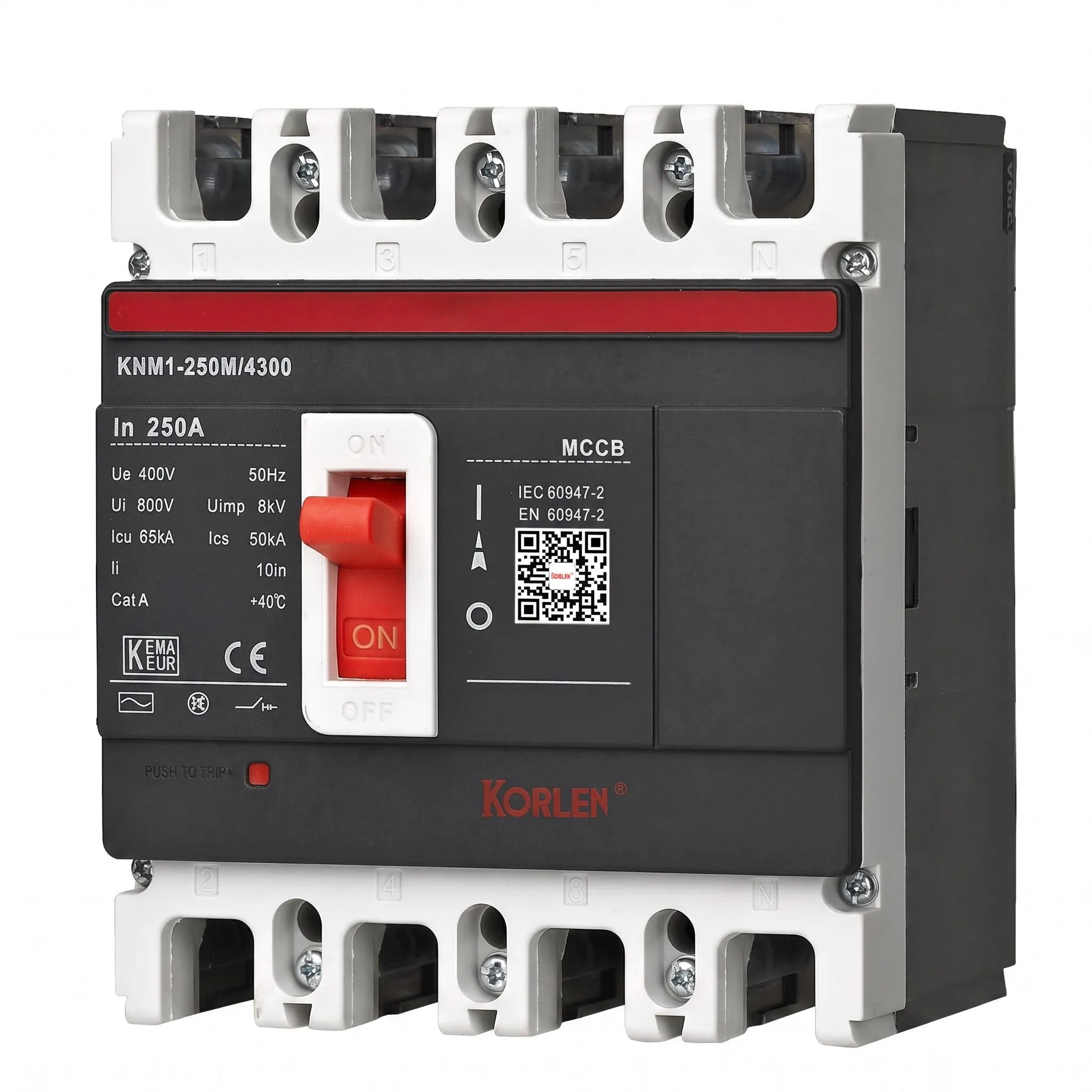 Compact Circuit Breaker 4P 2000A for Main Distribution KNM1 Korlen
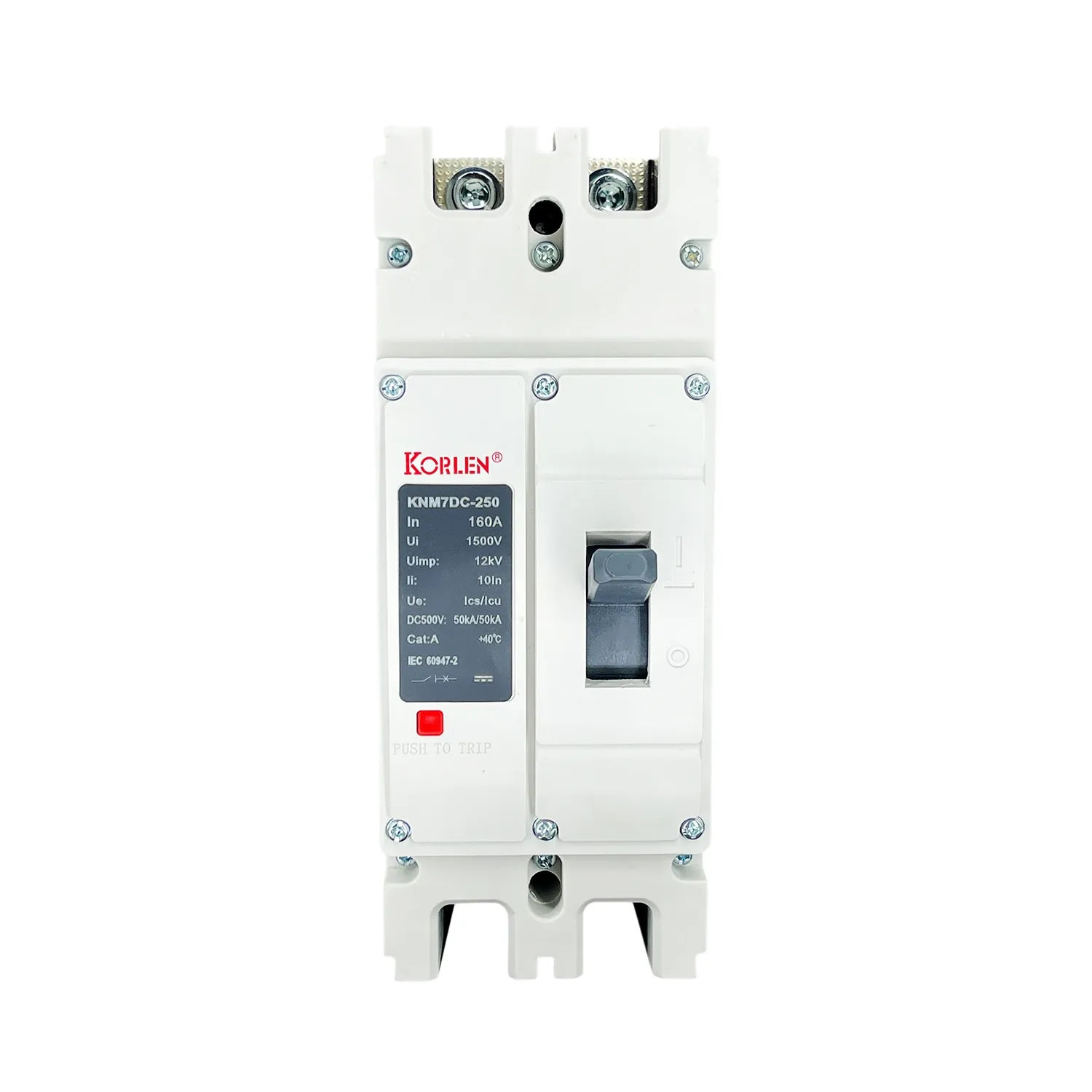 DC Compact Circuit Breaker 2 or 3 Pole 400–630A 500 V DC KNM7DC Korlen
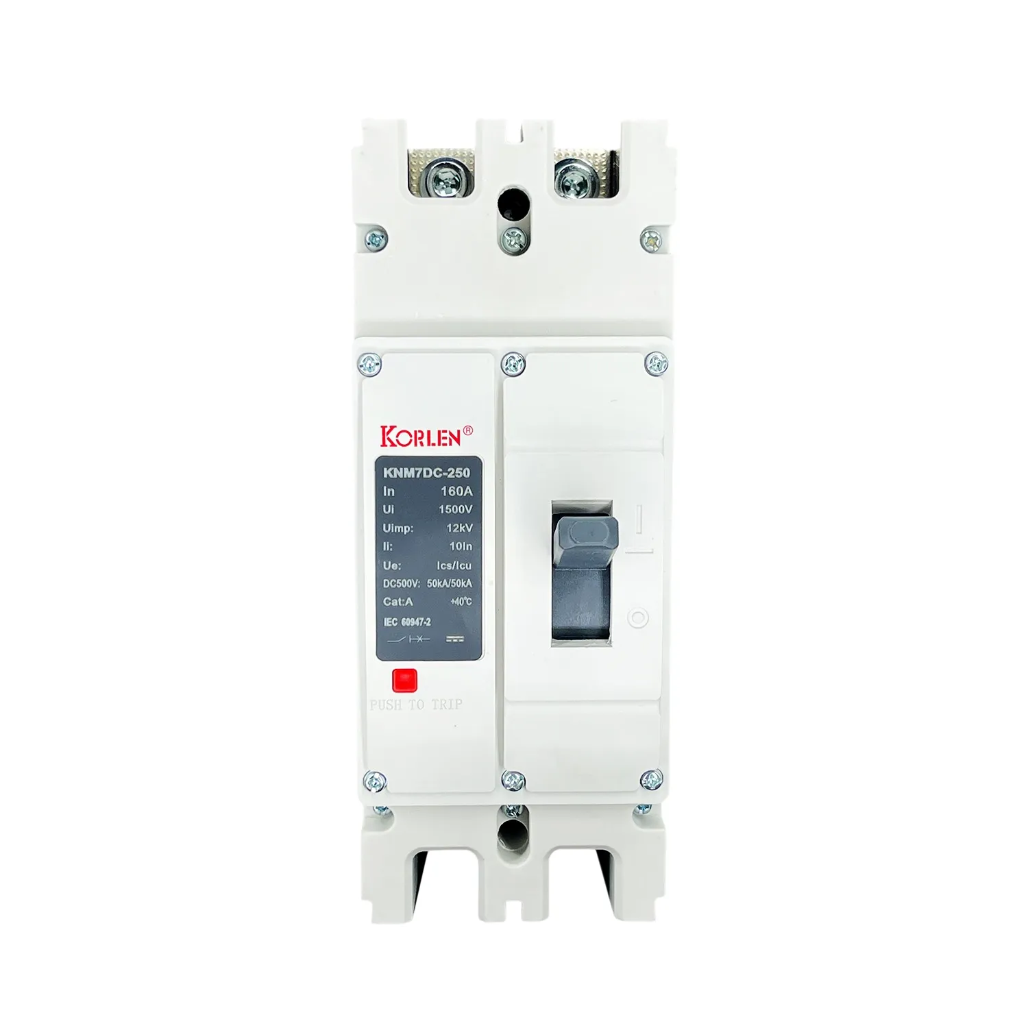 DC Compact Circuit Breaker 2P / 3P 400–630A 1500 V DC, for PV and Storage KNM7DC Korlen
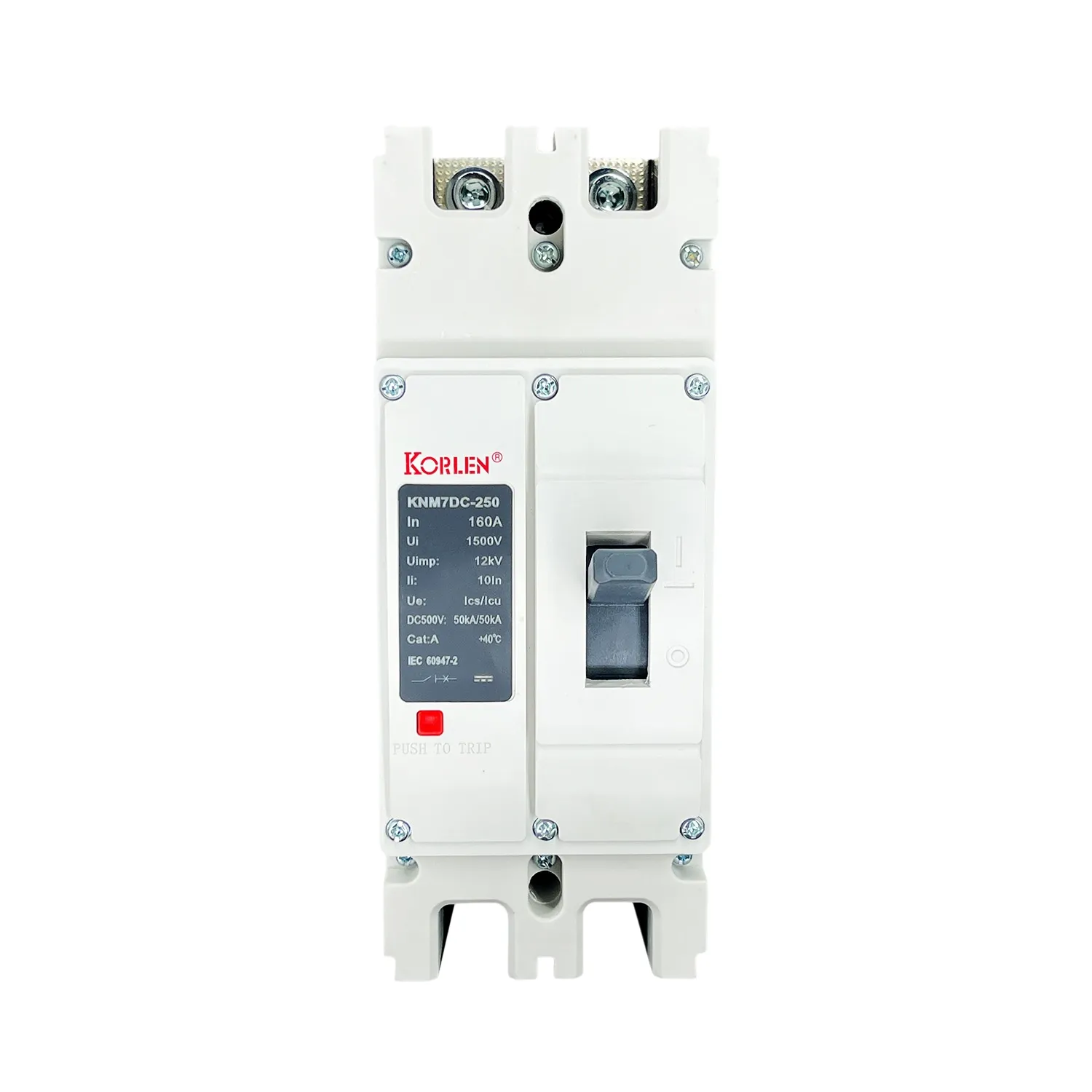 DC Compact Circuit Breaker 2P / 3P 400–630A for DC Distribution KNM7DC Korlen
Surge Protective DevicesType 1+2 surge arresters for AC distribution boards and DC PV arrays, Imax 10kA to 50kA, 2P and 4P, up to 1500V DC, for rooftop plants.All Products
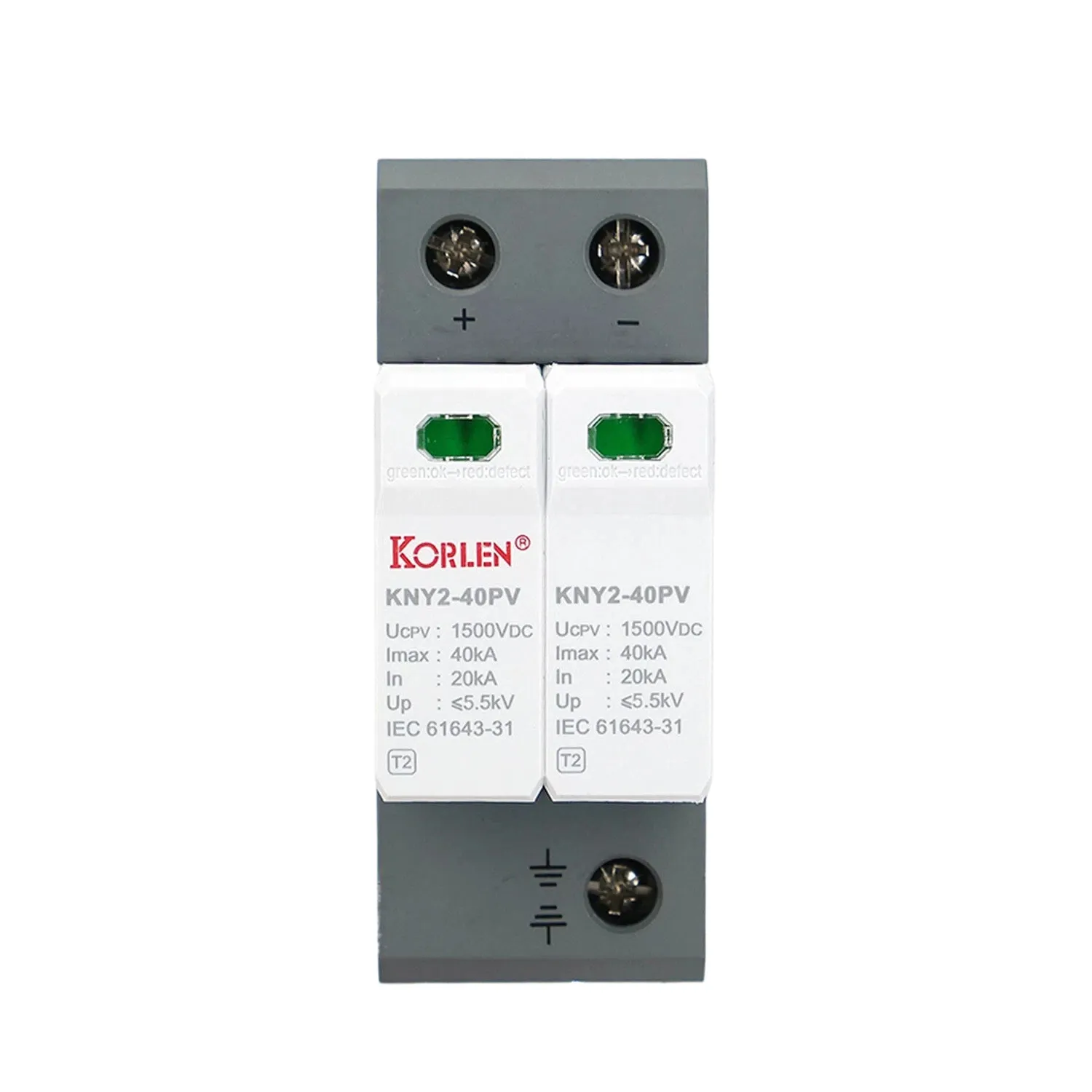 DC SPD Type 1+2 Imax 40kA 800 V DC 2P KNY2-40PV Korlen
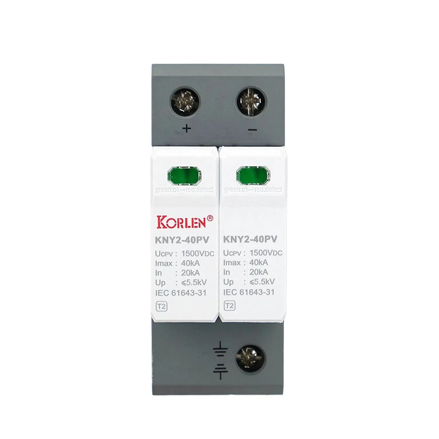 DC SPD Type 1+2 Up 4.5 kV 2P 1500 V DC KNY2-40PV Korlen
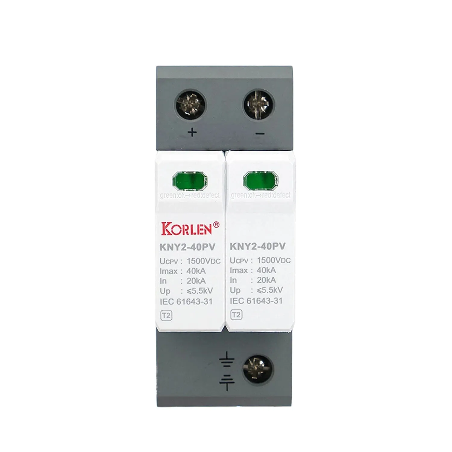 DC Surge Protection Device Type 1+2 1000 V DC 2P Imax 40kA KNY2-40PV Korlen
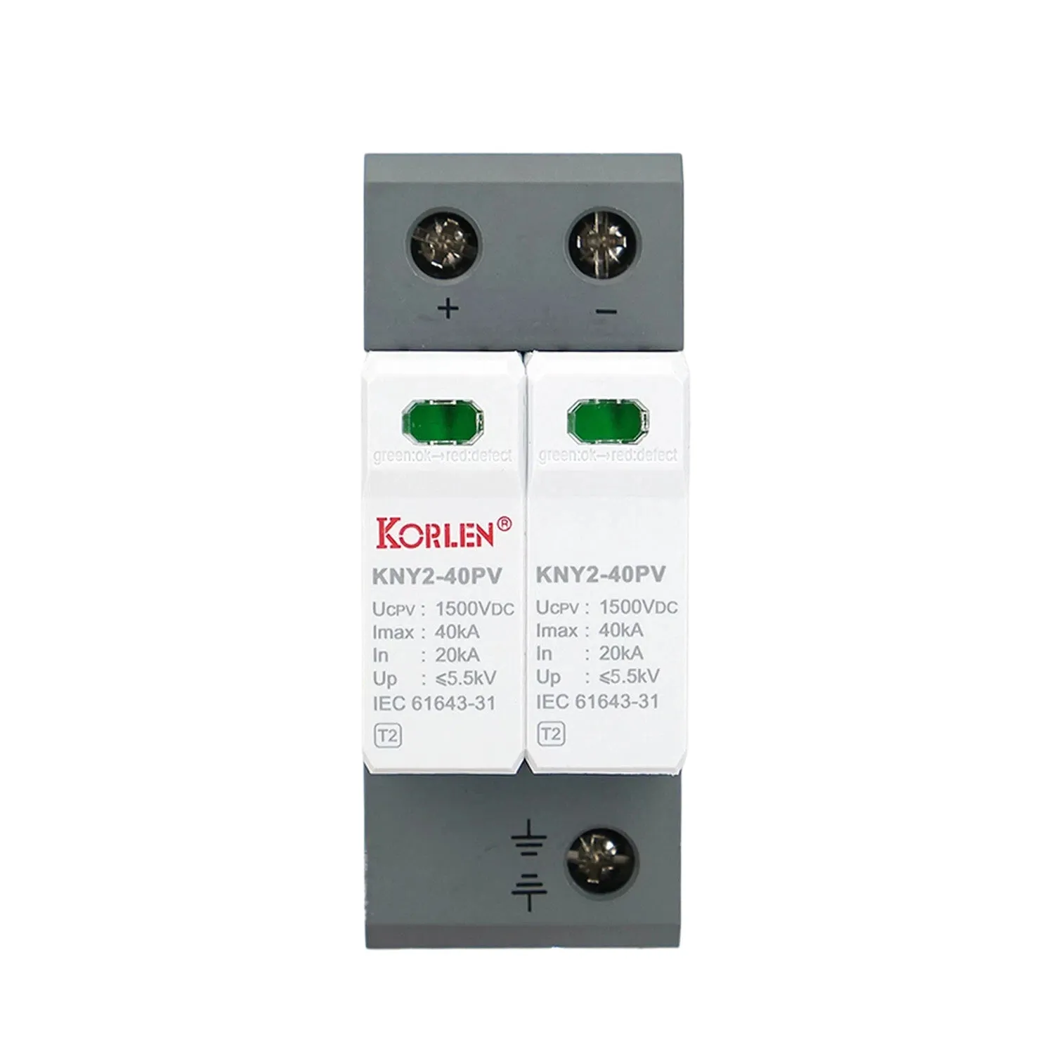 DC Surge Protection Device Type 1+2 Imax 40kA 2P 600 V DC KNY2-40PV Korlen
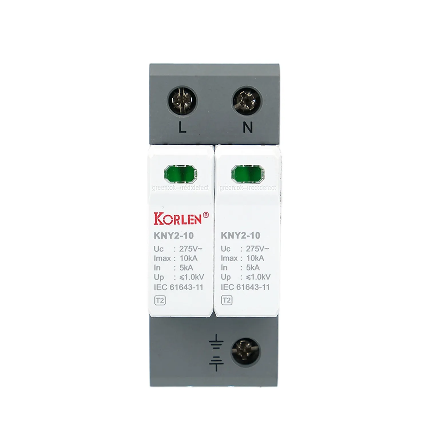 Double Pole Surge Arrester Type 1+2 Imax 50kA KNY2-10 Korlen
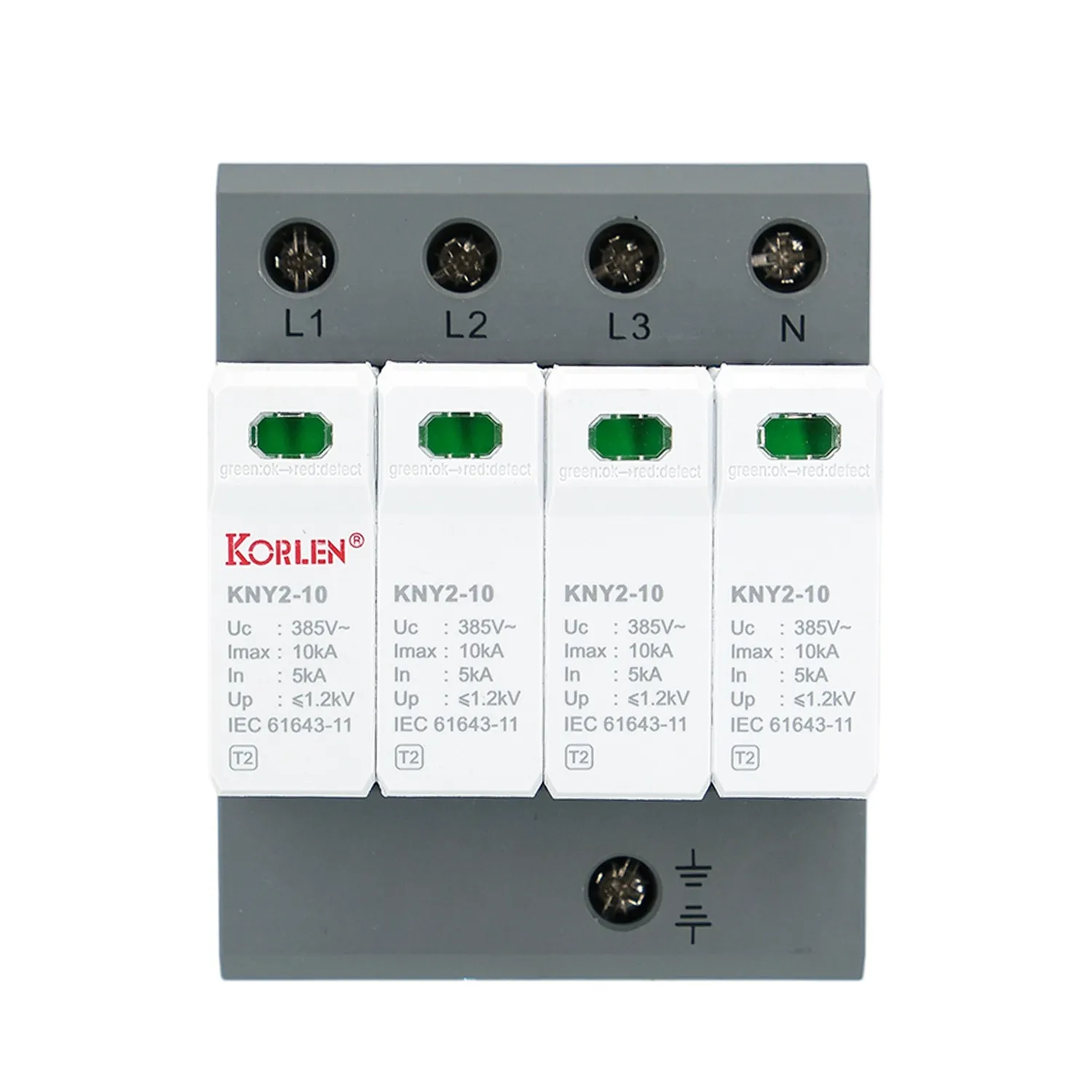 Four Pole Overvoltage Protection Device Type 2 Imax 10kA KNY2-10 Korlen
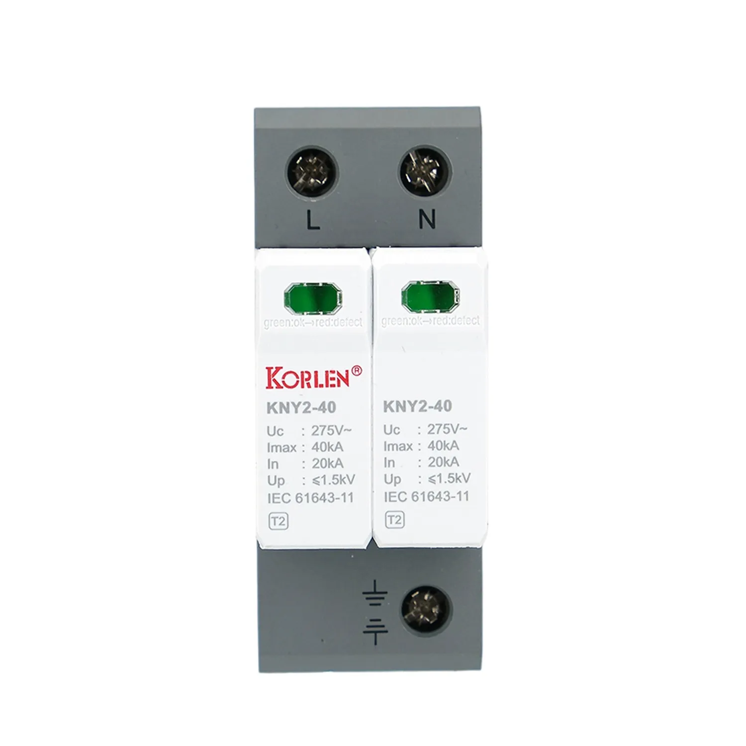 Overvoltage Protection Device Type 1+2 2P Up 1.5 kV KNY2-40 Korlen
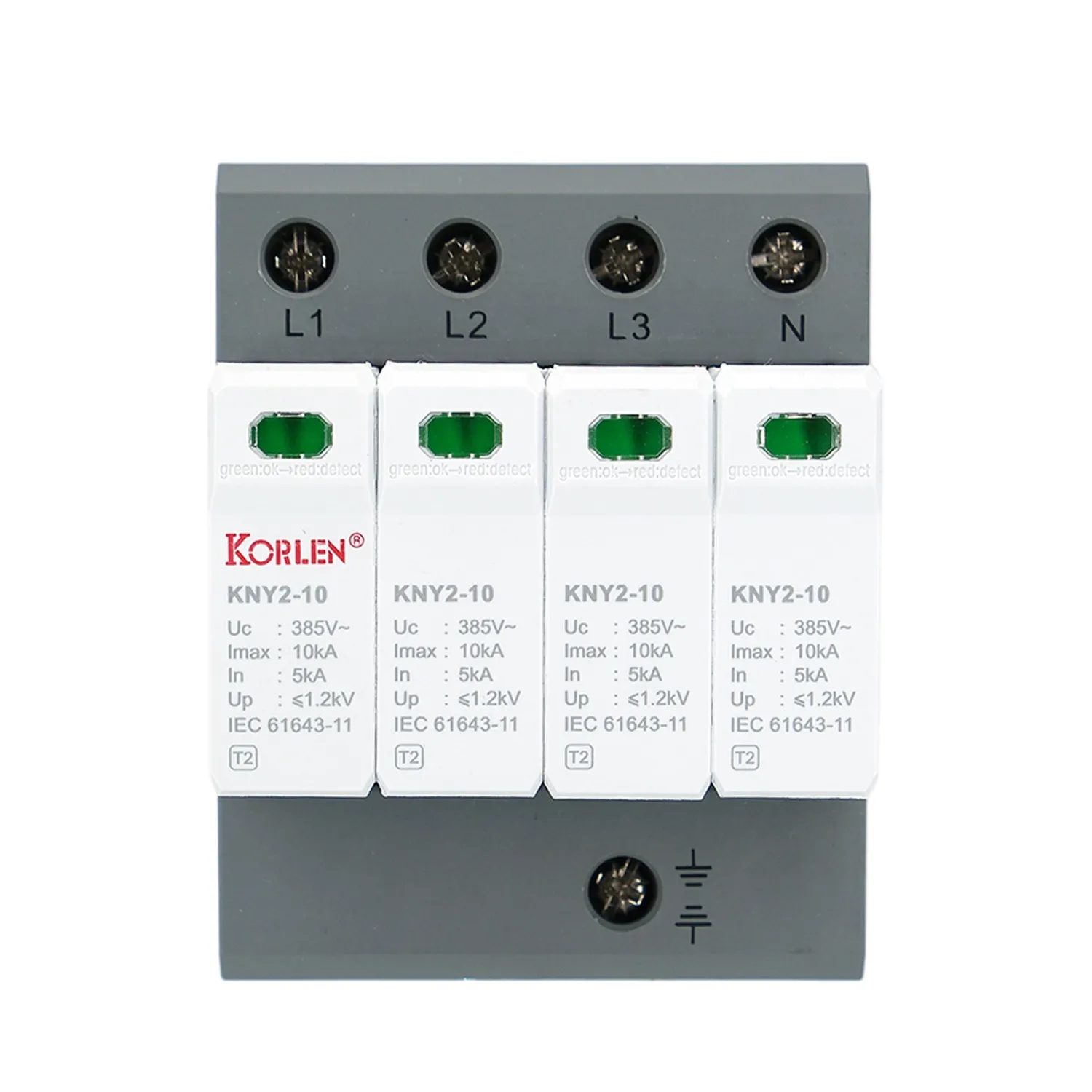 Overvoltage Protection Device Type 1+2 In 20kA 4P KNY2-10 Korlen
FusesFuse holders used on PV string protection.All Products
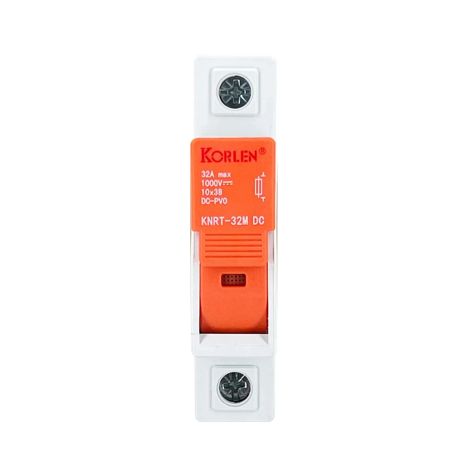 DC Fuse with Holder 1000 V DC 2–32A 10×38mm KNRT-32M Korlen
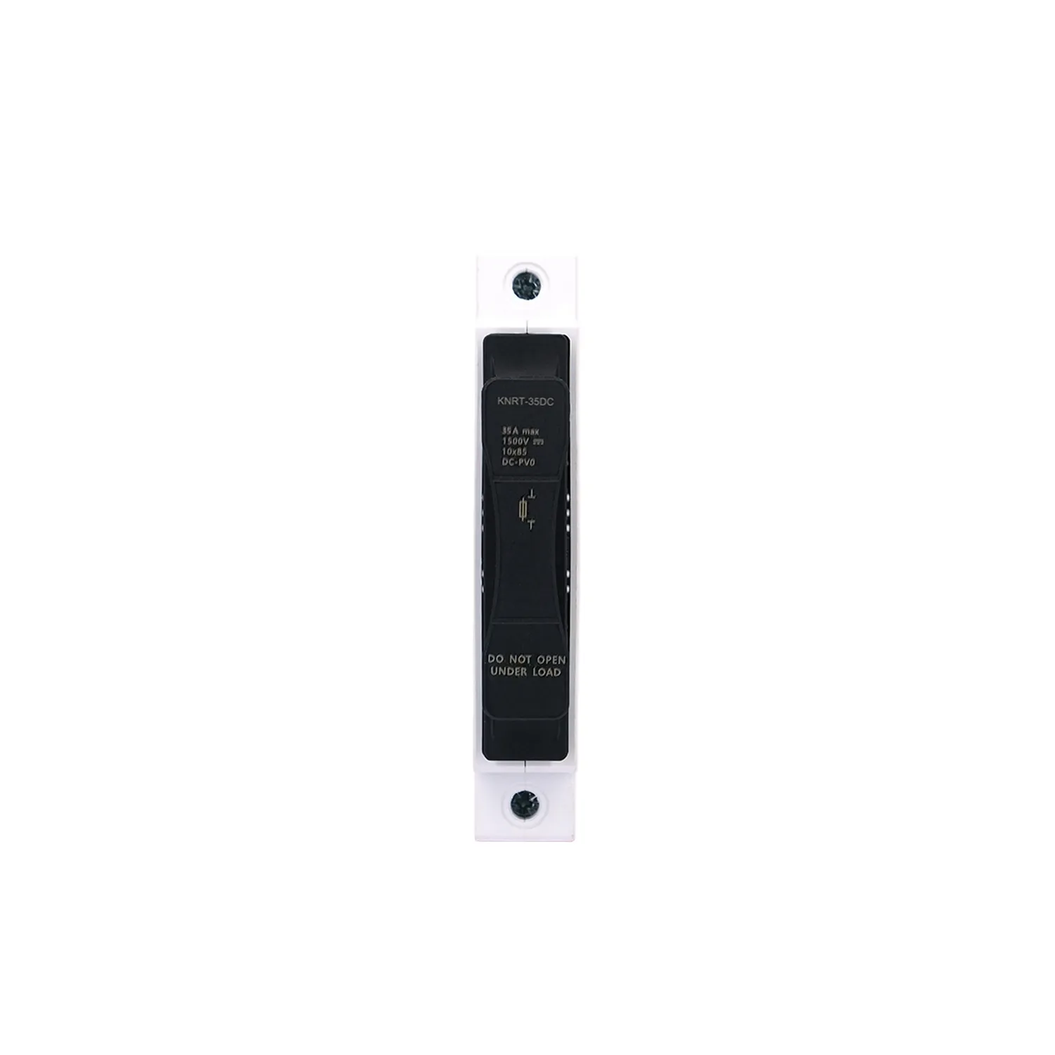 gPV Fuse and Base 1500 V DC 1–35A KNRT-35DC Korlen
Isolating SwitchesLoad-break and isolating switchesAll Products
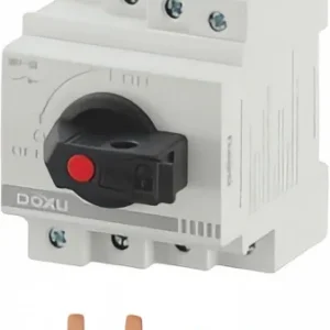 32A DC Load Break Switch 300 V DC DS1-32 Doxu
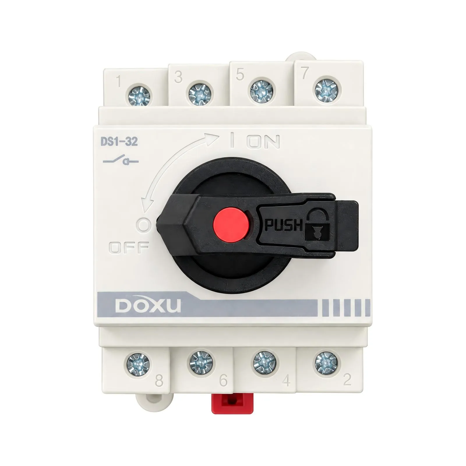 32A PV Isolating Switch 1000 V DC 2P DS1-32 Doxu
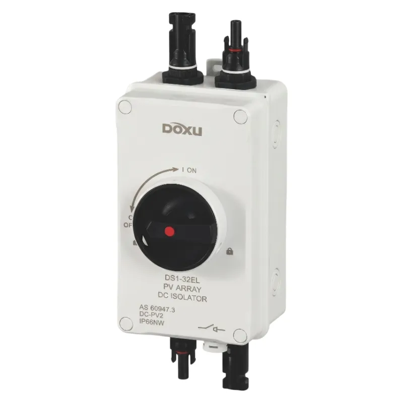 32A Solar DC Disconnect Switch 1200 V DC DS1-32EL/2-MC4-H Doxu
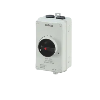 DC Isolator Switch 1200 V DC 16–32A DS1-32EL/4P Doxu
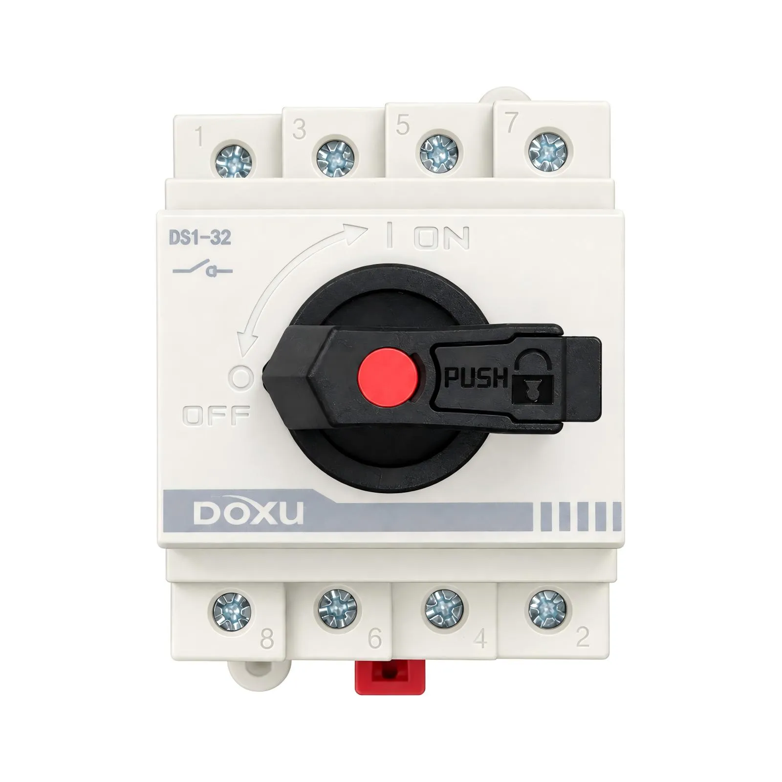 DC Isolator Switch 300 V DC 32A 2P DS1-32 Doxu
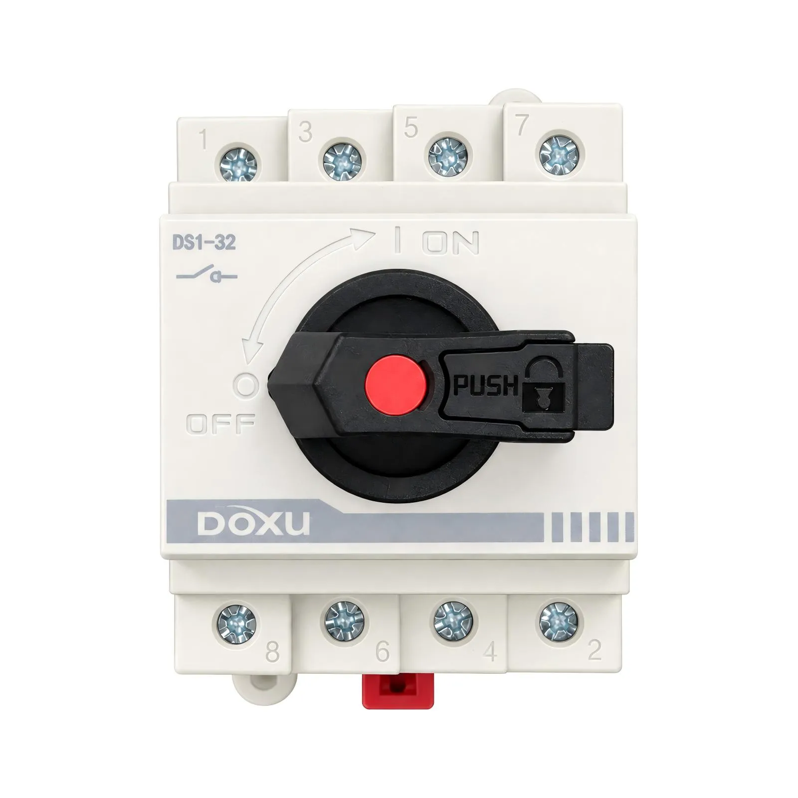 DC Isolator Switch 4P 32A 1000 V DC DS1-32 Doxu
 DC Isolator Switch 600 V DC 32A DS1-32 Doxu
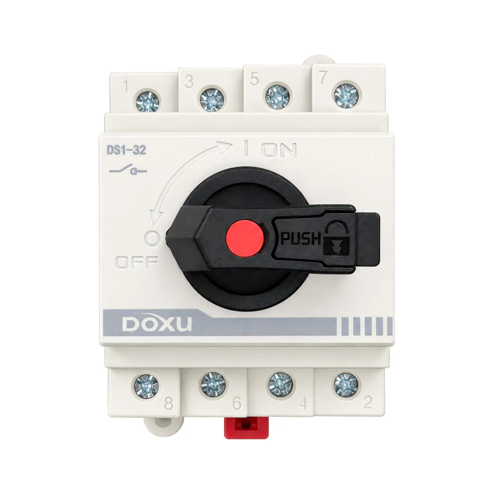 DC Load Break Switch 1200 V DC 2P 32A DS1-32 Doxu
Contactors & Motor StartersContactors, thermal relays and startersAll Products
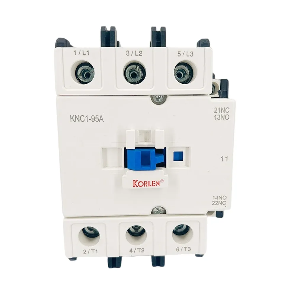 AC Contactor 3P 9–95A 660 V AC KNC1 Korlen
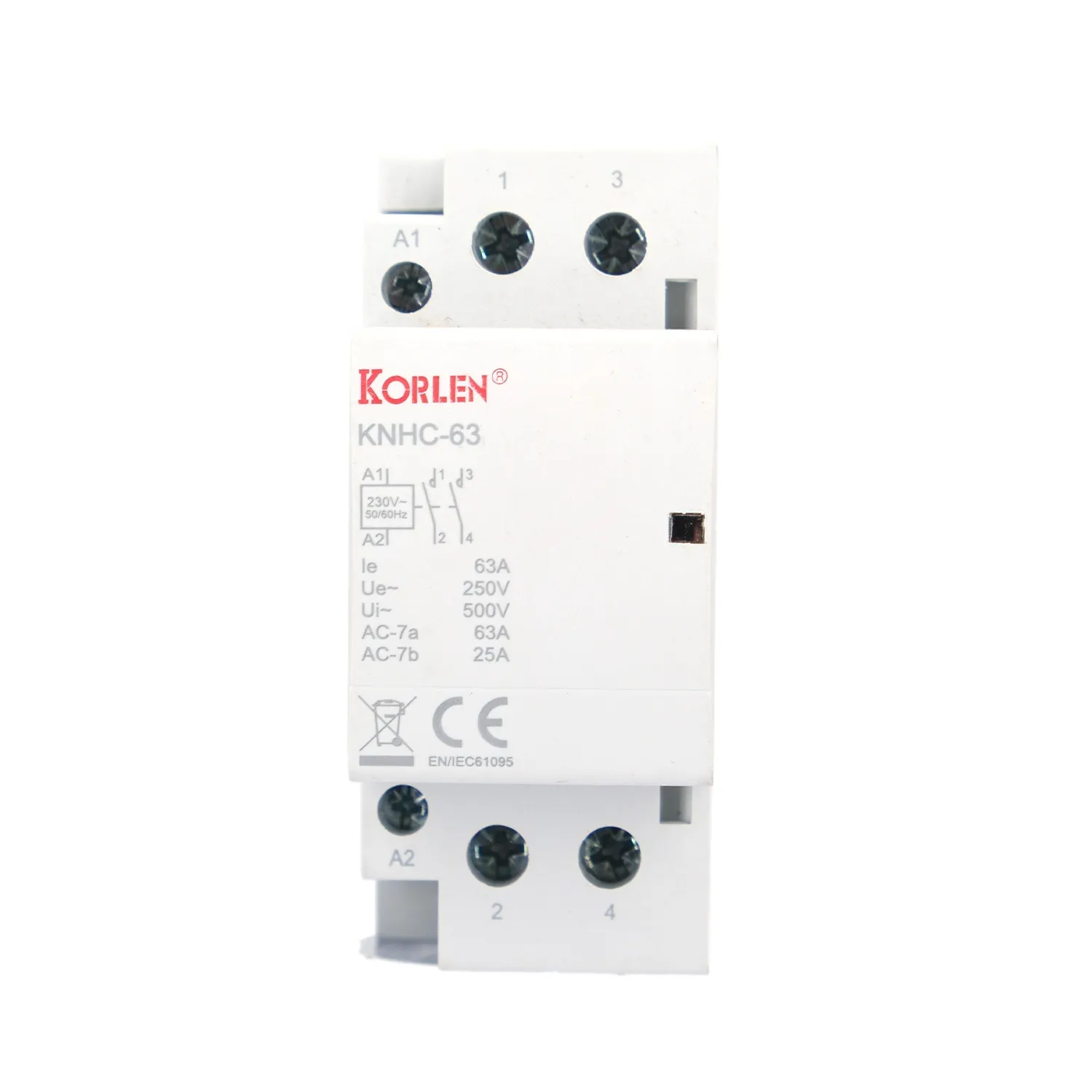 Building Automation Contactor 16–25A 3P 400 V AC KNHC Korlen
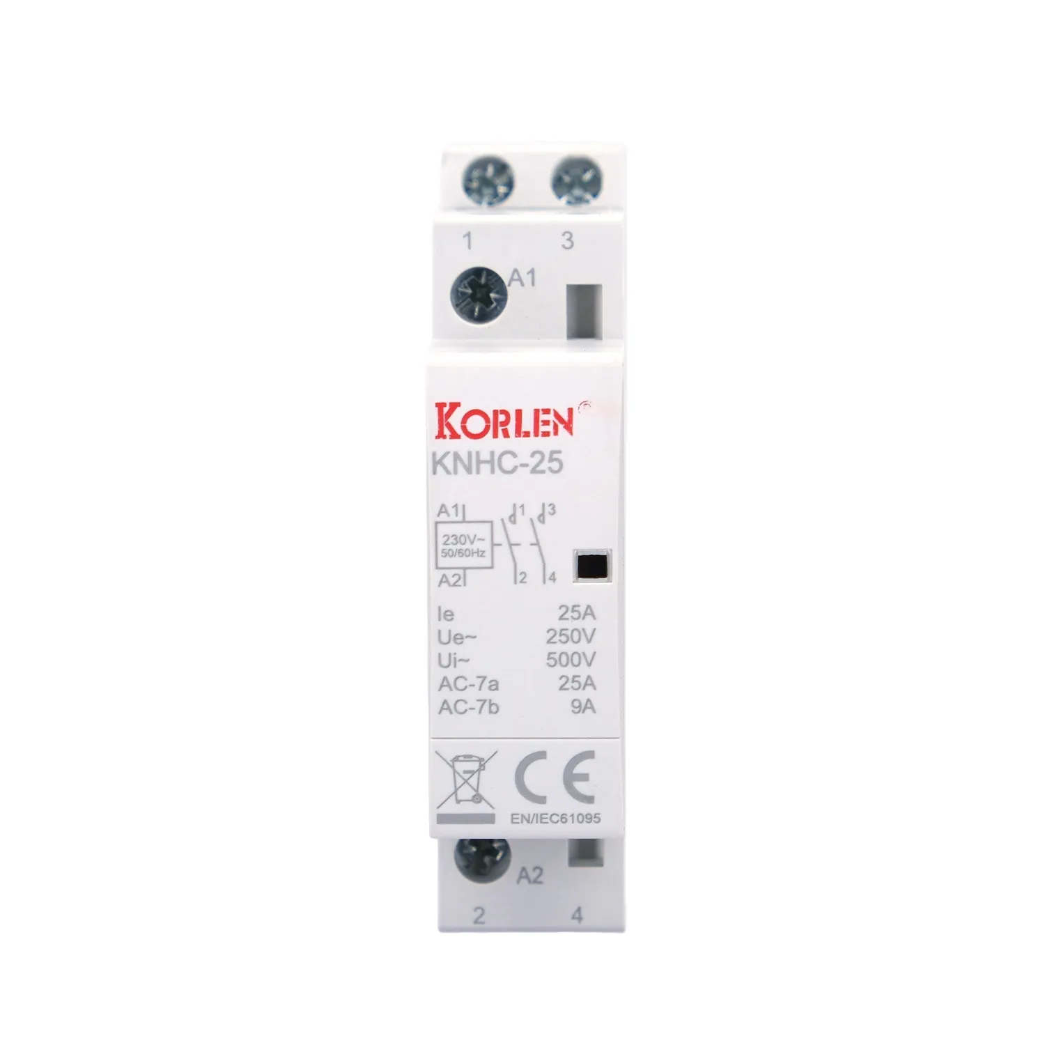 Building Automation Contactor 1P 32–63A for Building Services KNHC Korlen
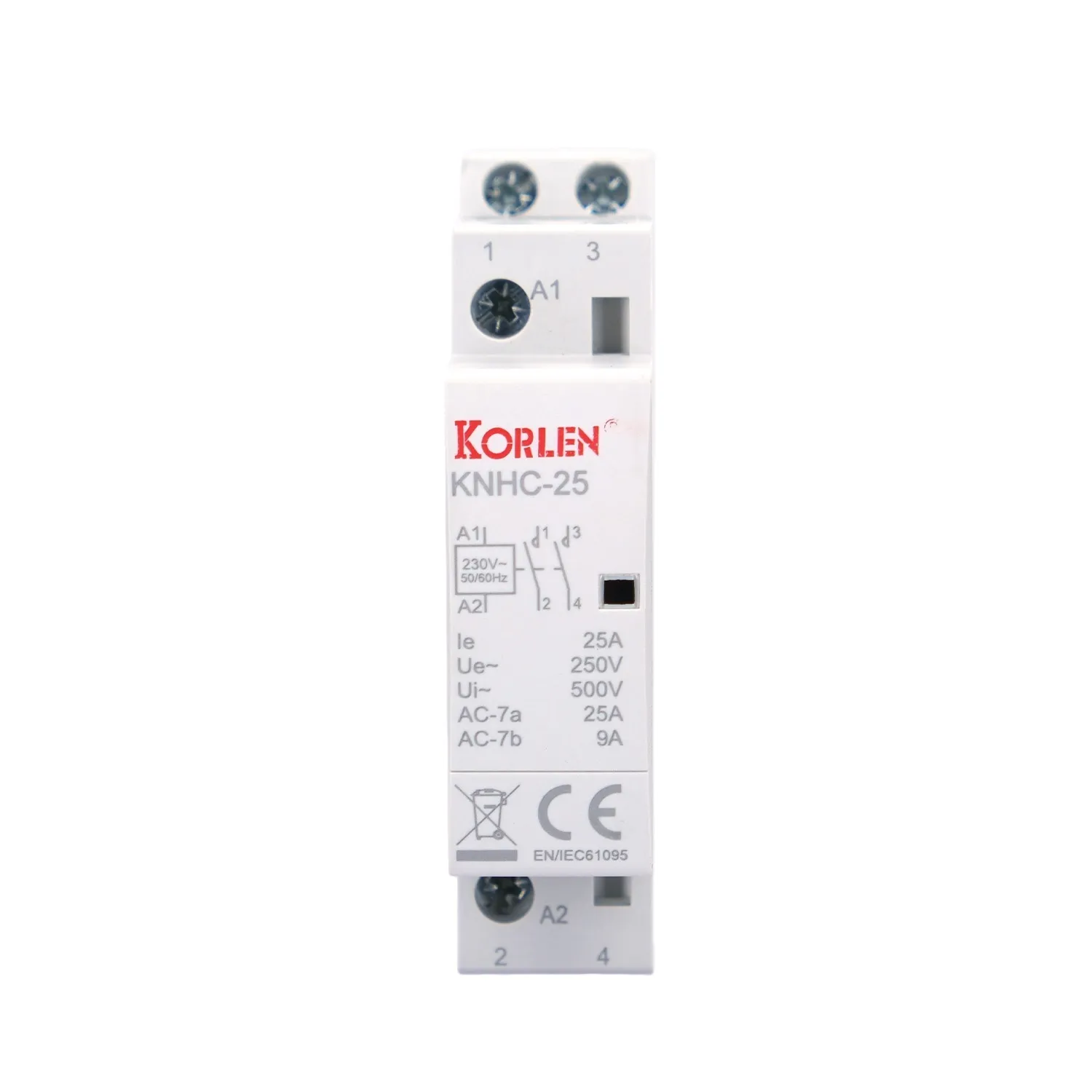 DIN Rail Contactor 1P 80–125A up to 400 V AC KNHC Korlen
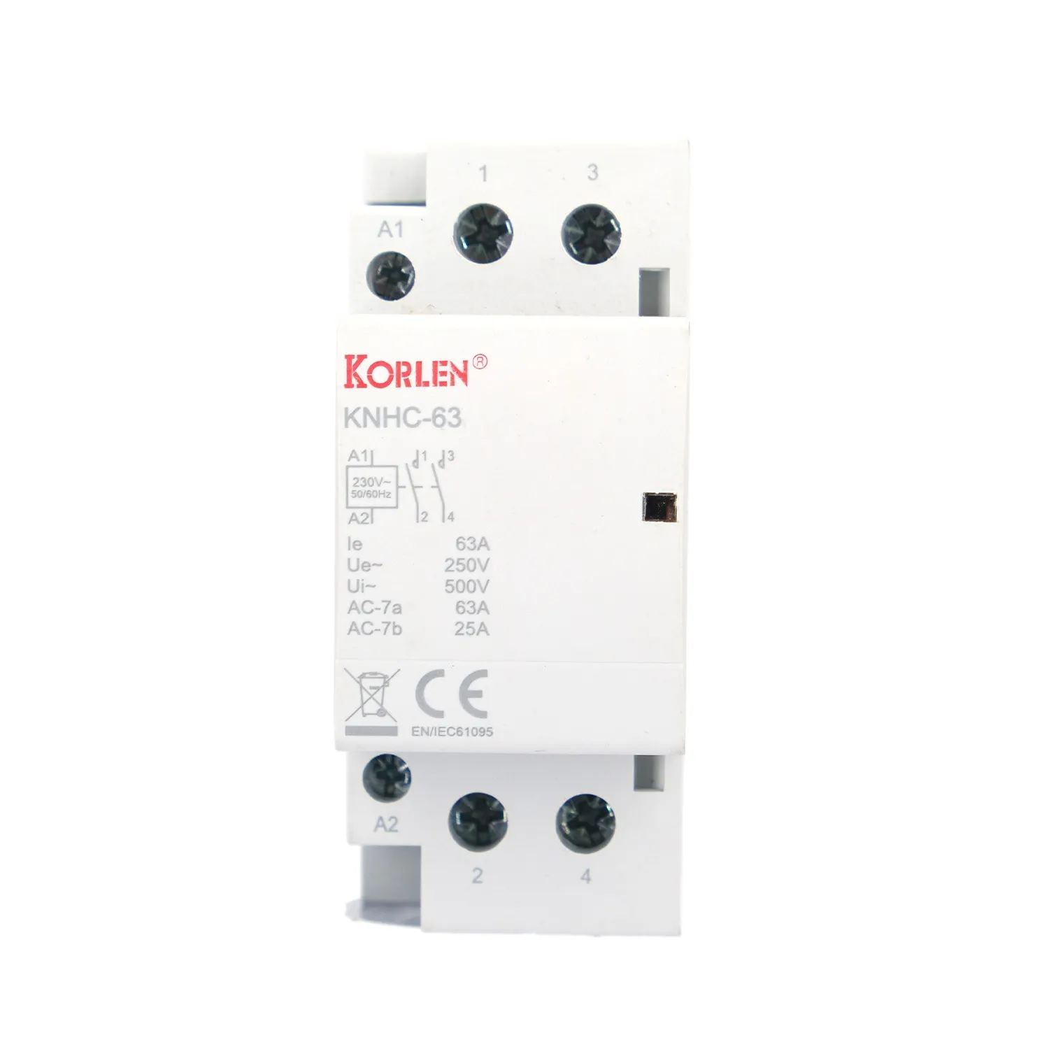 DIN Rail Contactor 3P 32–63A 400 V AC KNHC Korlen
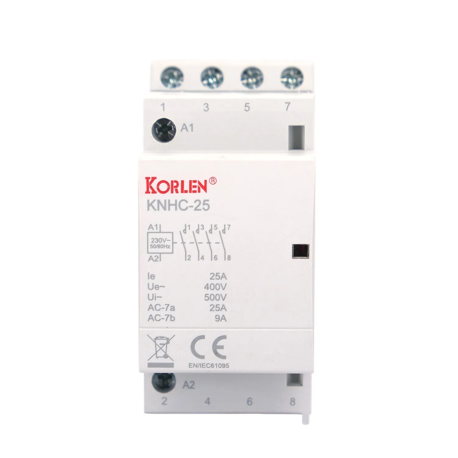 Double Pole Modular Contactor Relay 32–63A up to 400 V AC KNHC Korlen
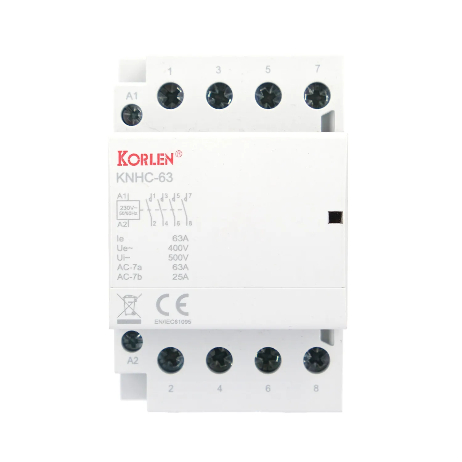 Four Pole Building Automation Contactor 80–125A up to 400 V AC KNHC Korlen
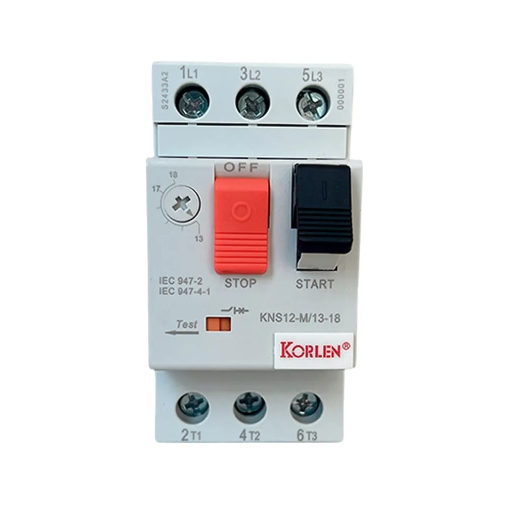 Manual Motor Starter 3P 1–80A 690 V AC KNS12 Korlen
Combiner & Distribution BoxesEnclosures for string combining and AC distribution.All Products
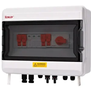 DC Combiner Box 2 in / 2 out 1000 V DC for PV Plants KNX5PV-H/B-2/2 Korlen
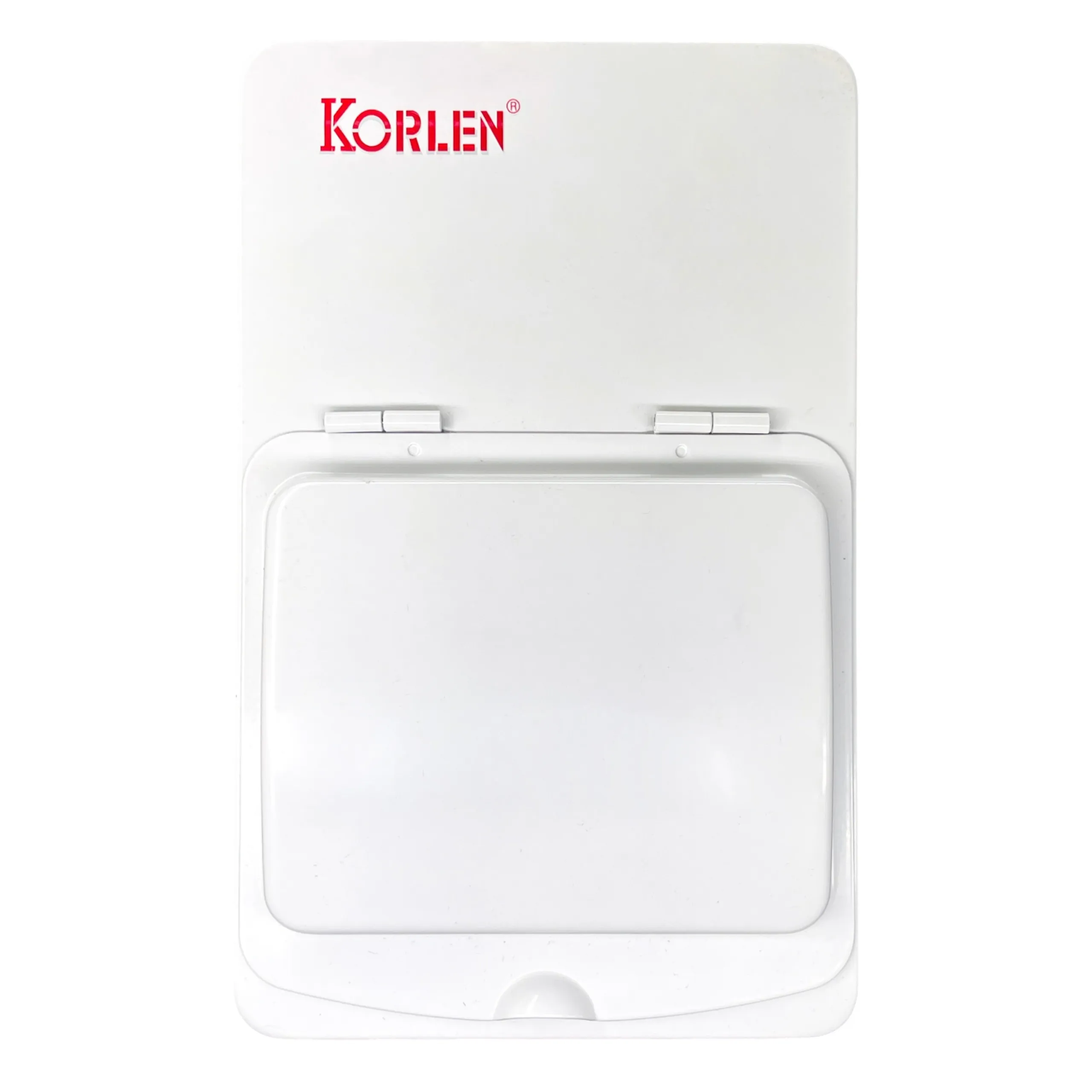 Distribution Board 6–36 modules Watertight Enclosure KNS Korlen
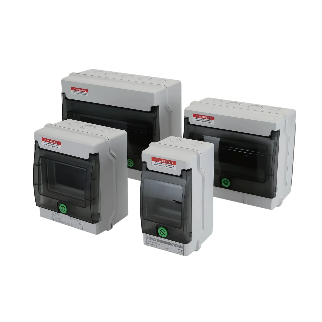 Distribution Board IP65 4–24 modules KNHA Korlen
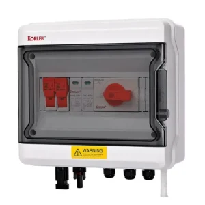 PV Combiner Box 1000 V DC 1 in / 1 out KNX5PV-H/B-1/1 Korlen
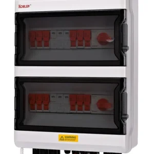 PV Combiner Box 1000 V DC 4 in / 2 out KNX5PV-H/B-4/2 Korlen
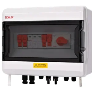 PV String Combiner Box 2 in / 1 out 1000 V DC KNX5PV-H/B-2/1 Korlen
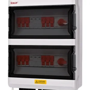 PV String Combiner Box 6 in / 2 out 1000 V DC, KNX5PV-H/B-6/2 Korlen
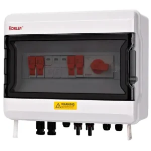 Solar String Combiner Box 3 in / 1 out 1000 V DC KNX5PV-H/B-3/1 Korlen
RCBOSingle module RCBOs combining overcurrent and residual current protection, 1P+N, 10A to 63A, 10kA, for final circuits in consumer units.All Products
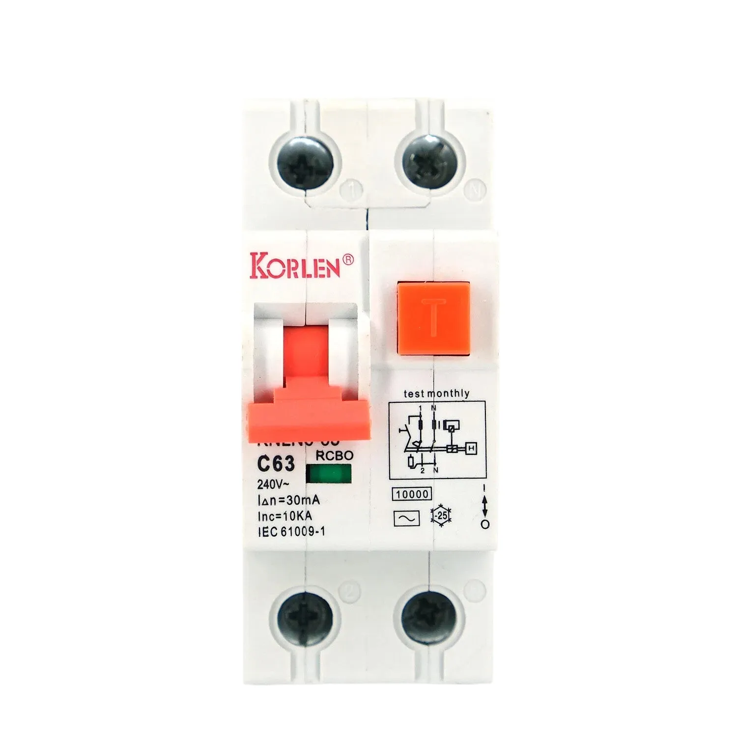 RCBO 1P+N 10–63A 10kA KNLN6-63 Korlen
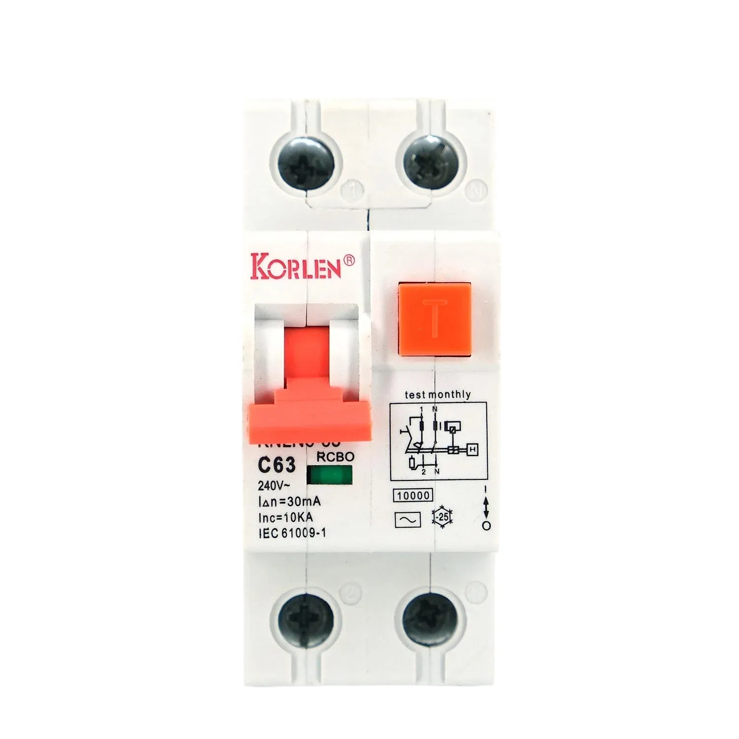 RCBO Circuit Breaker 1P+N 10–63A for Final Circuits KNLN6-63 Korlen
Residual Current Circuit BreakersTwo and four pole RCCBs from 63A to 125A, Type A, B and AC, for earth leakage protection in single and three phase distribution boards.All Products
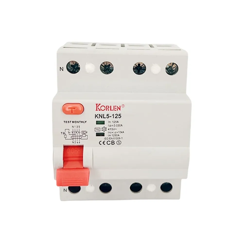 100–125A RCCB 4P Type A KNL5-125 Korlen
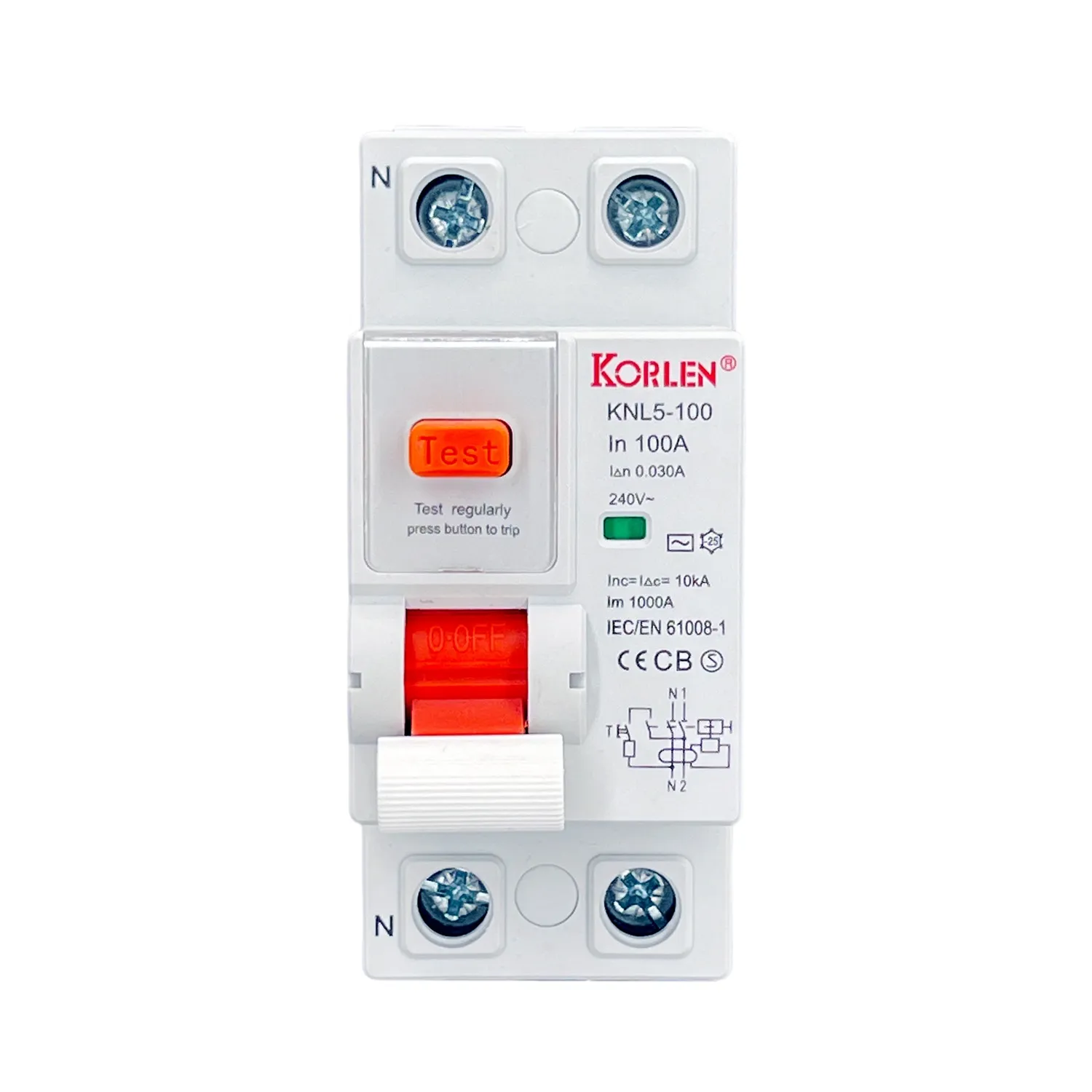 2P RCCB Circuit Breaker Type B 100–125A KNL5-100 Korlen
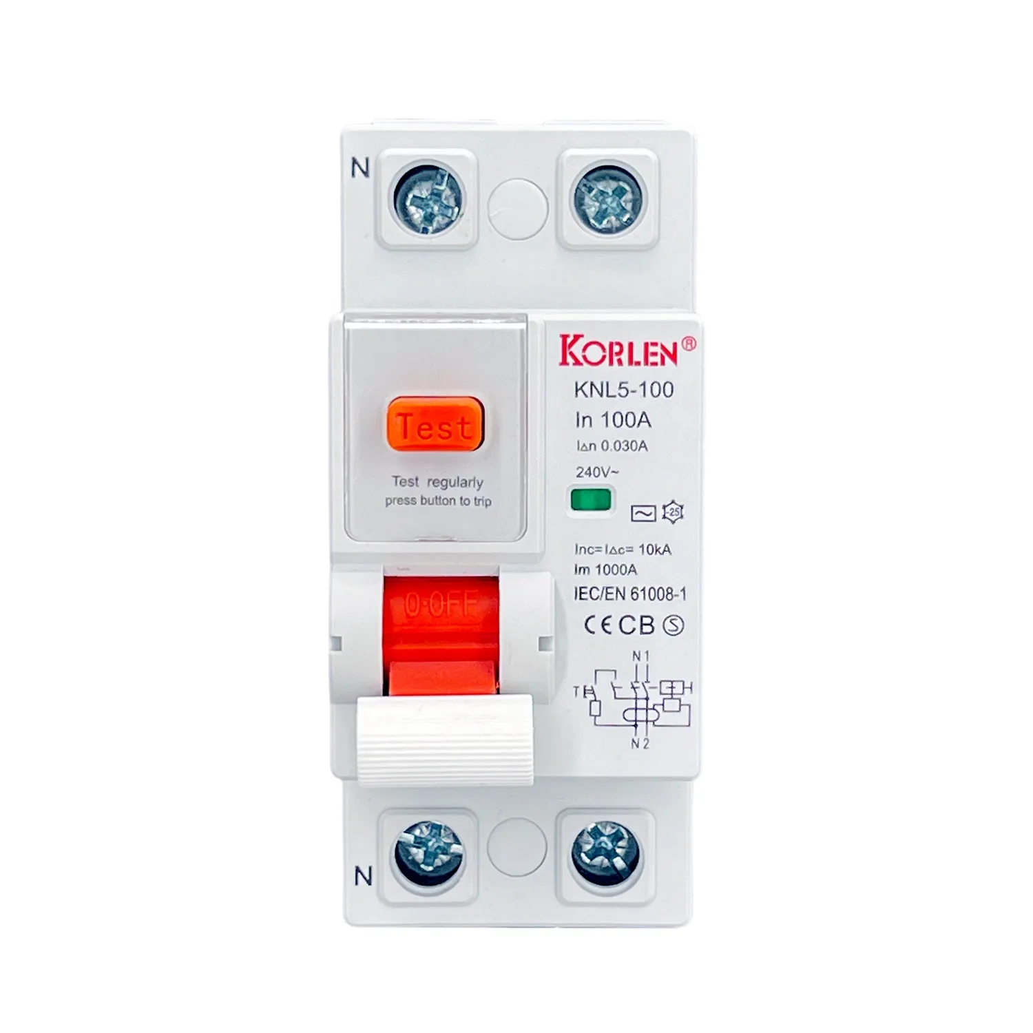 2P Residual Current Circuit Breaker Type A 63–100A KNL5-100 Korlen
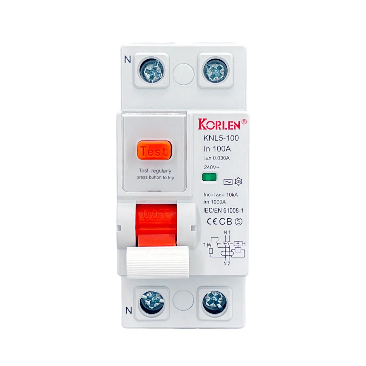 63–100A Residual Current Circuit Breaker 2P Type B KNL5-100 Korlen
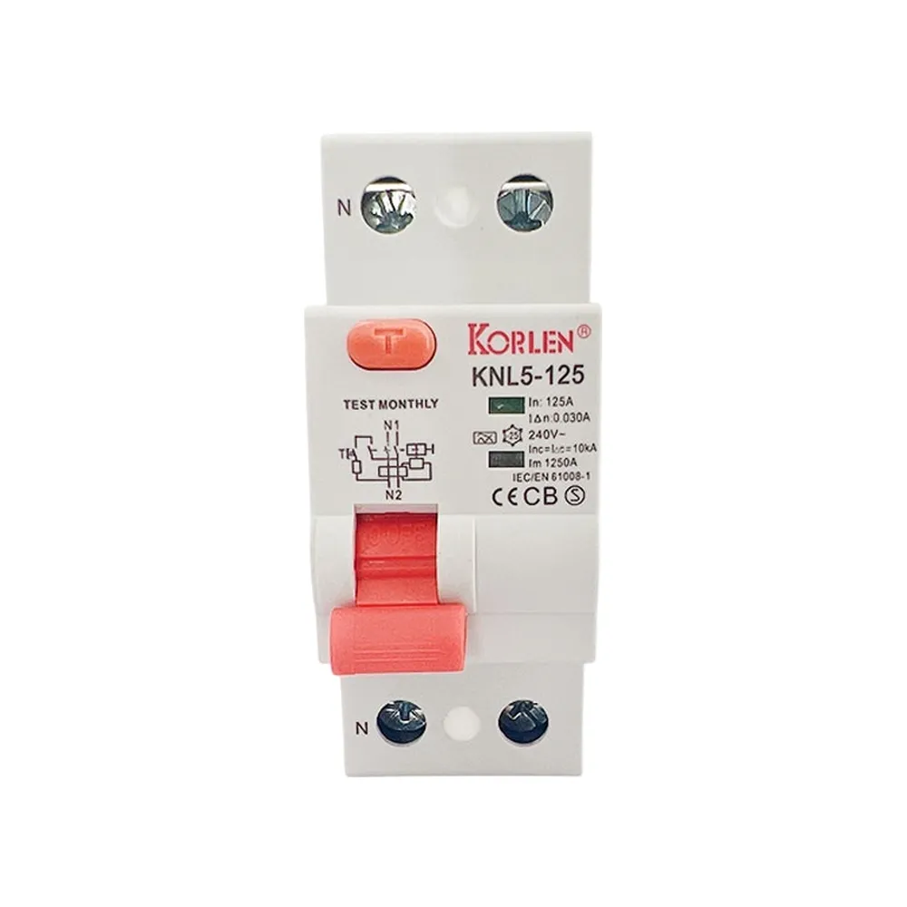 Double Pole Residual Current Breaker 100–125A Type A KNL5-125 Korlen
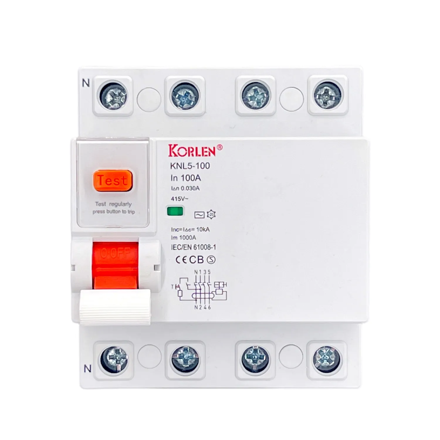 Four Pole RCCB 100–125A Type A KNL5-100 Korlen
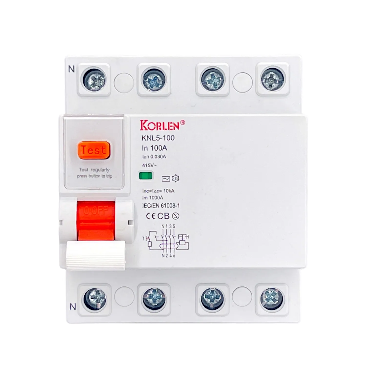 RCCB 4P 100–125A, Type AC KNL5-100 Korlen
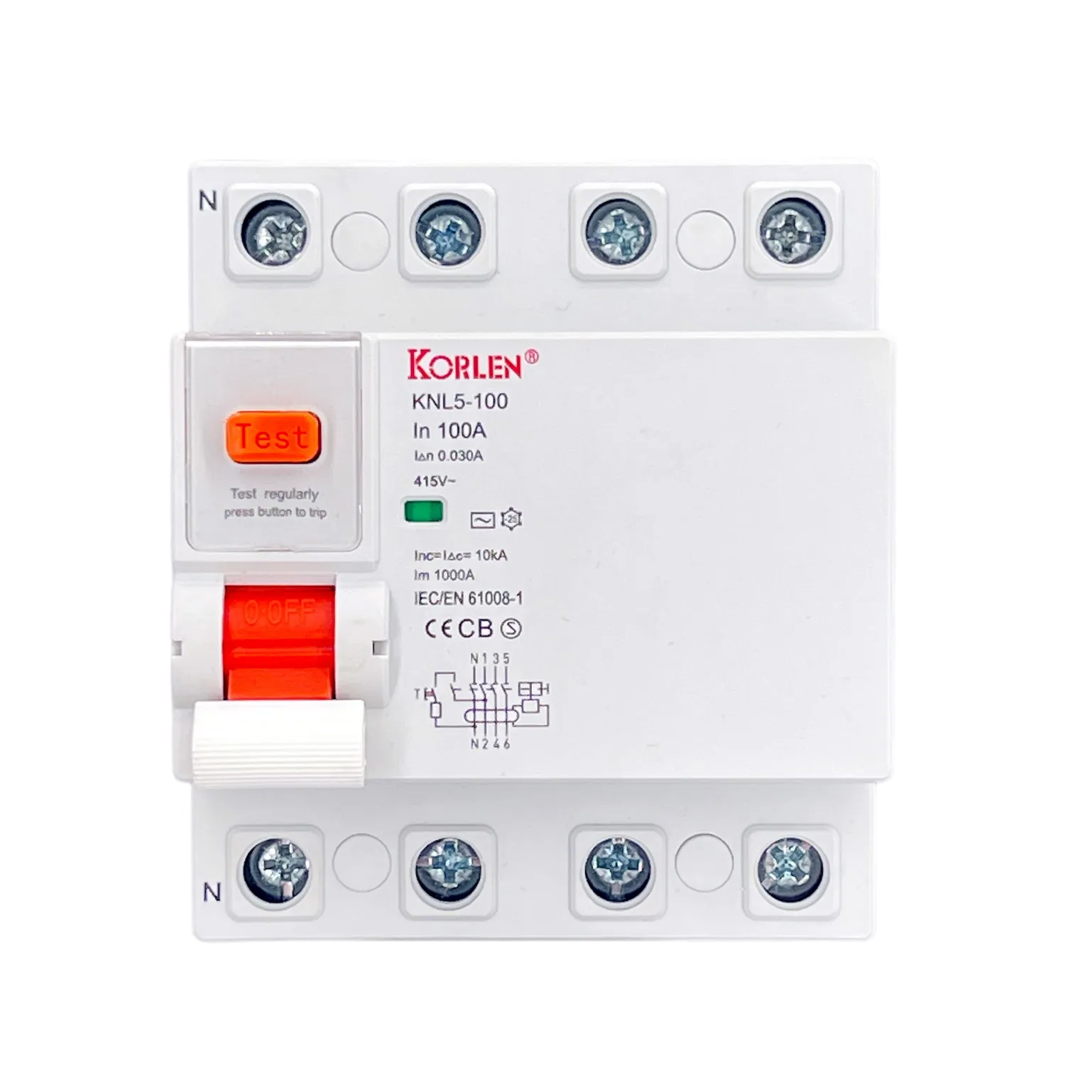 RCCB 4P Type B 100–125A KNL5-100 Korlen
Cable GlandsIP68 nylon cable glands in PG7 to PG63 and M8 to M114 threads, PA66 body, for waterproof cable entry on enclosures.All Products
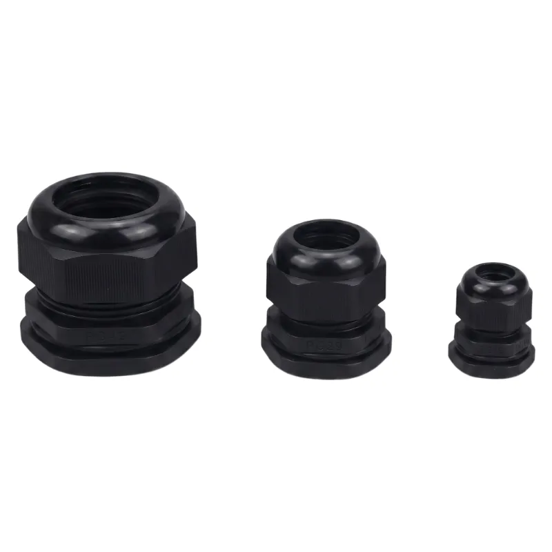 Cable Gland IP68 PA66 nylon PG7-PG63 WZCHDA
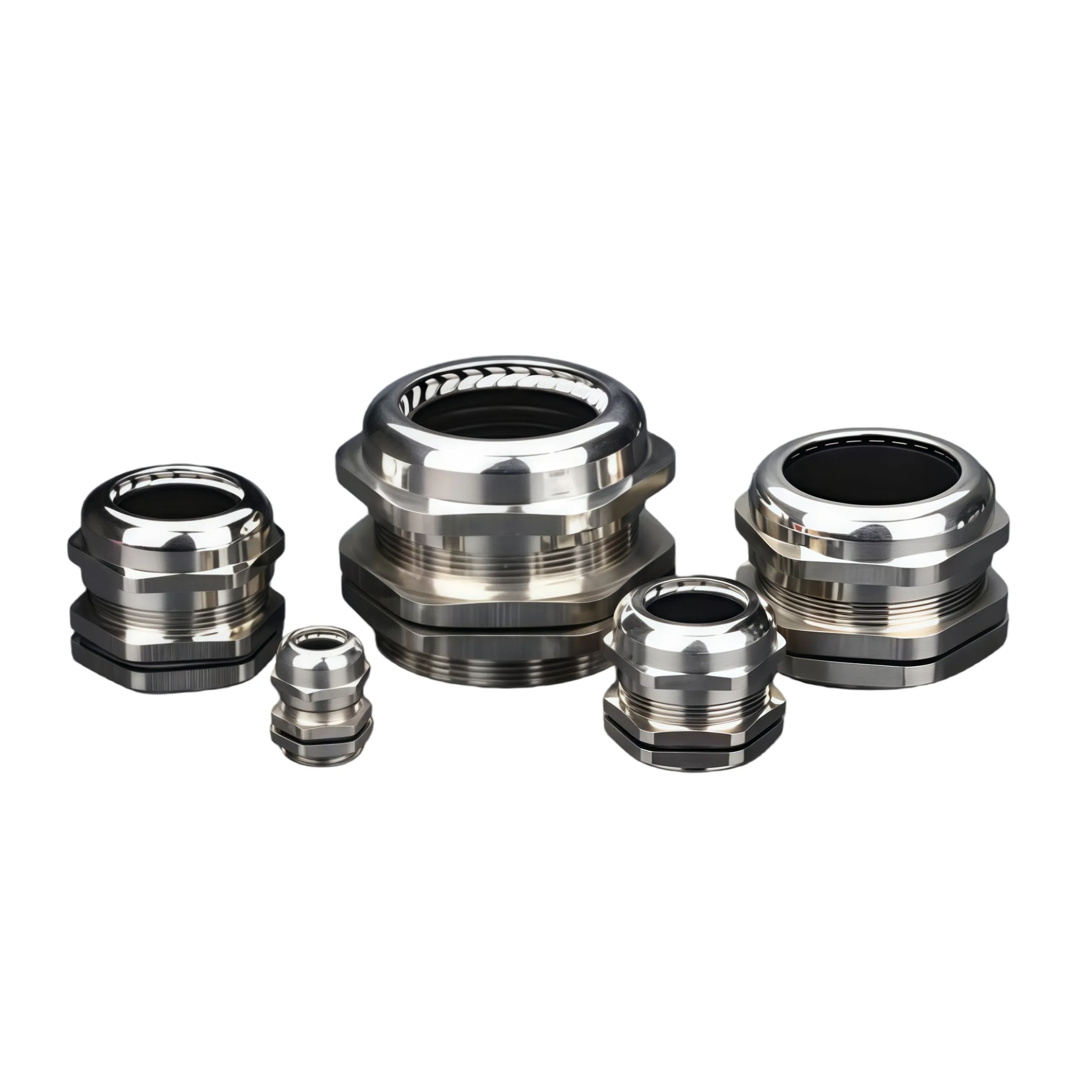 Nylon Cable Gland IP68 PG7-PG63 PG thread WZCHDA
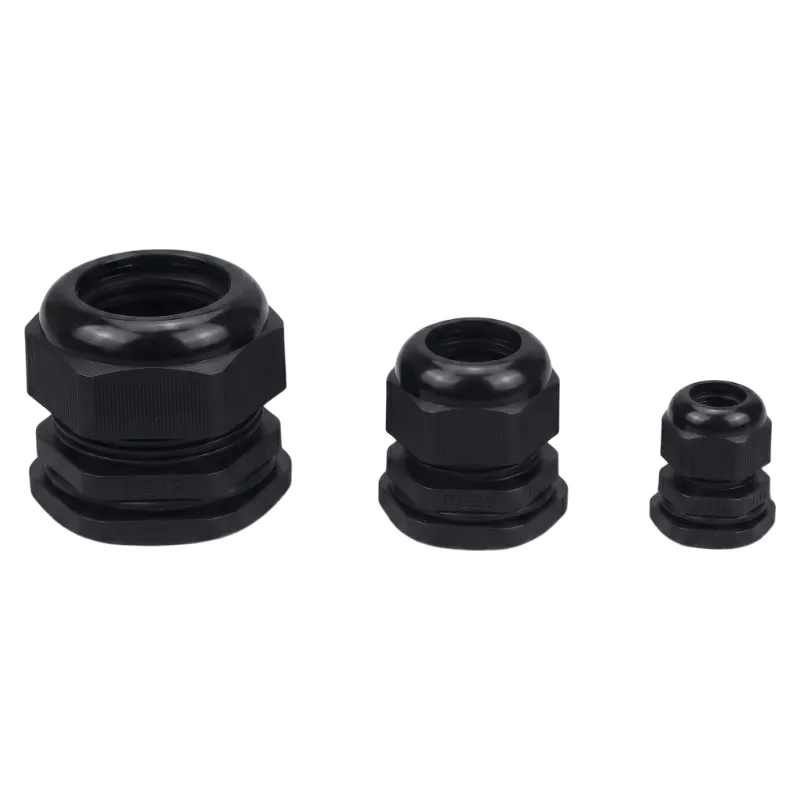 PA66 Cable Gland metric M thread M8-M114 IP68 WZCHDA
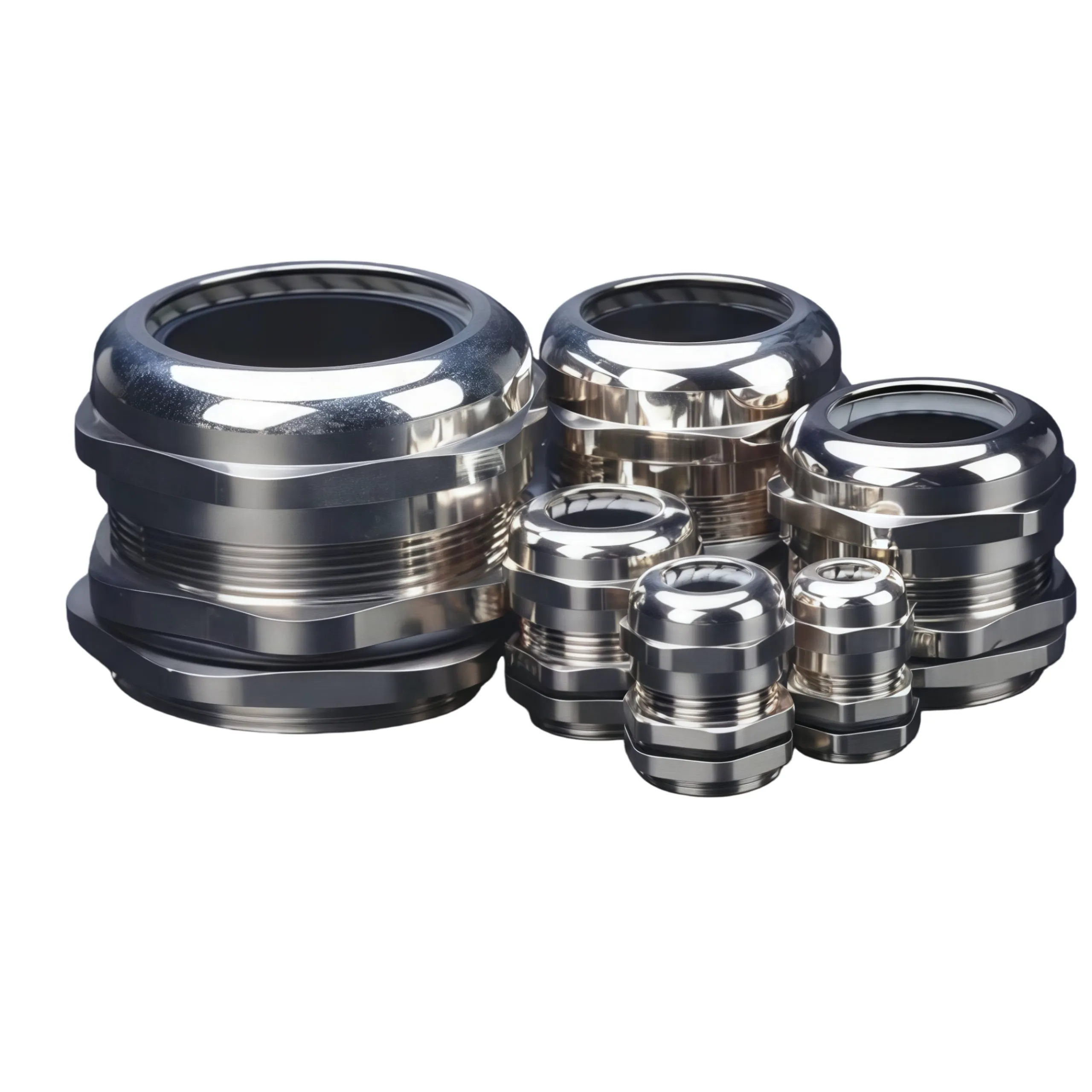 Waterproof Cable Gland IP68 metric M thread WZCHDA
Cable TiesNylon 66 cable ties from 60 to 1500mm, plus stainless steel SS304 and SS316 ties, PVC coated and double head versions.All Products
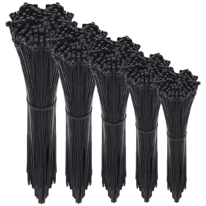 Cable Tie Nylon 66 1.9-10 mm 60-1500 mm ZHEJIN
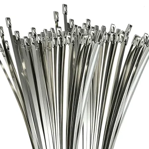 Heavy Duty Cable Tie SS304 / SS316 stainless steel 4.6-12 mm ZHEJIN
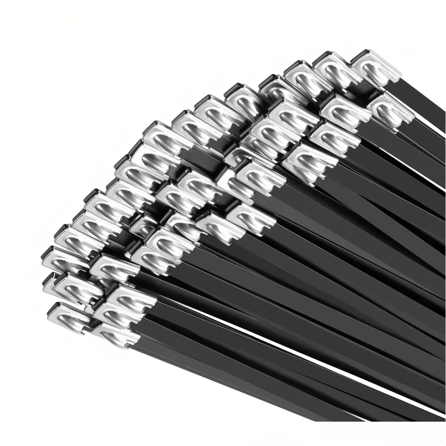 Metal Cable Tie PVC Coated SS304 / SS316 4.6-12 mm ZJS-PC ZHEJIN
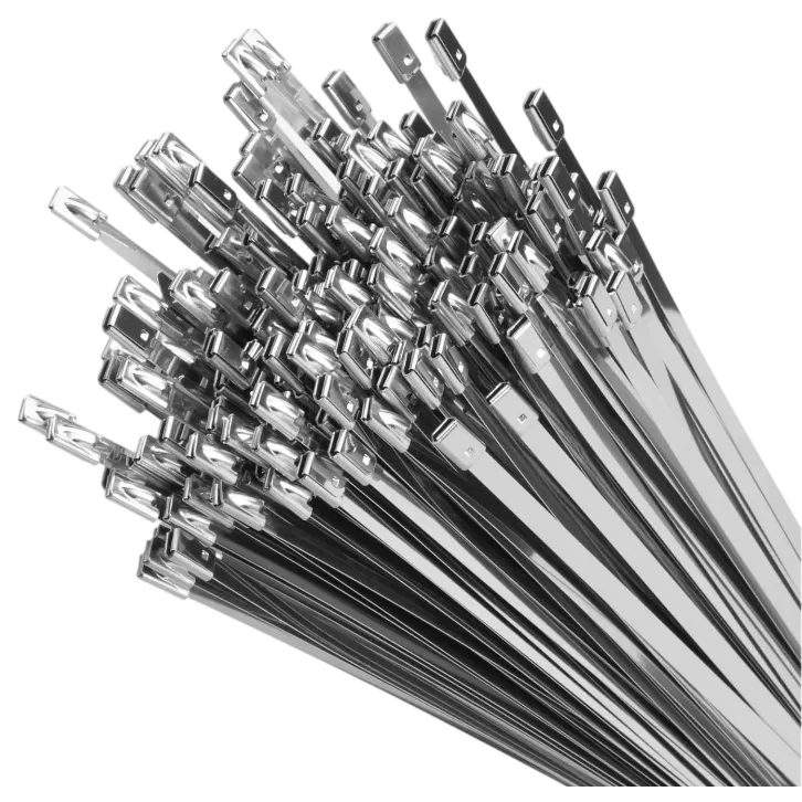 SS Cable Tie 12.3 / 16 / 25 mm ZJDS Double Head Heavy Duty ZHEJIN
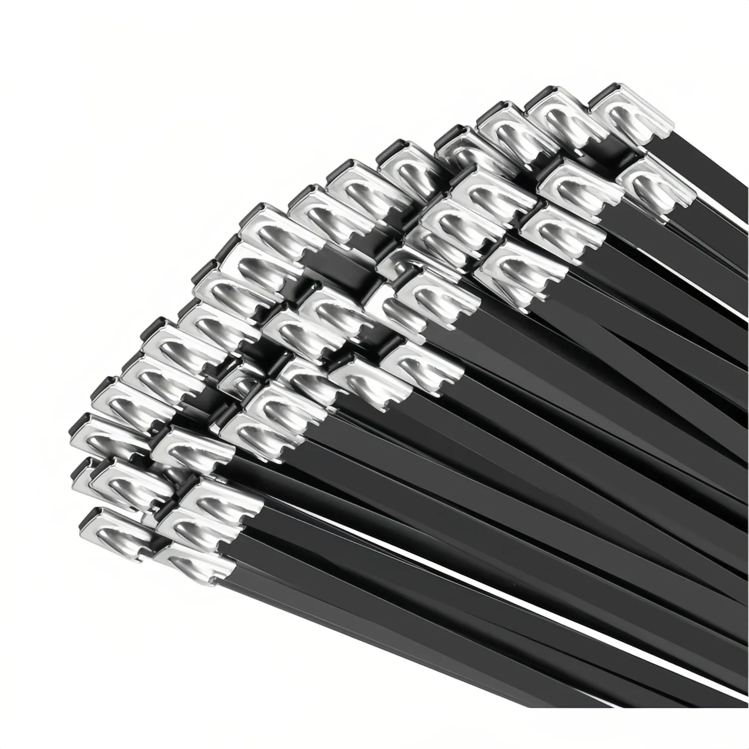 Stainless Steel Cable Tie in SS304 / SS316 ZJS-BC ZHEJIN
Corrugated ConduitFlexible corrugated conduit in PA66 nylon and polyethylene, AD7 to AD54.5, black, for cable routing in panels.All Products
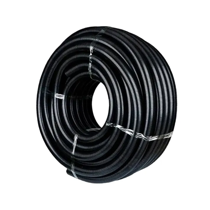 PA66 Corrugated Conduit AD10-AD54.5 nylon Black WZCHDA
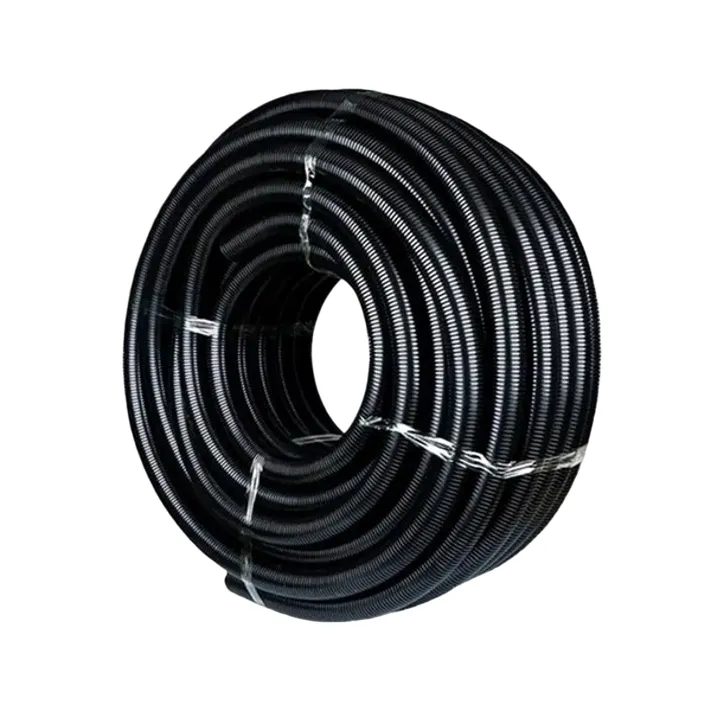 PE Corrugated Conduit polyethylene AD7-AD54.5 WZCHDA
Solar ConnectorsPhotovoltaic cable connectors rated 1000V and 1500V DC, 30A to 65A, IP67, for solar string connections and module wiring.All Products